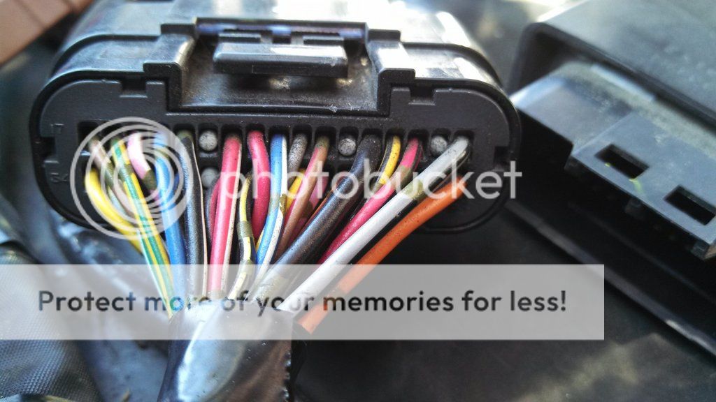
I grabbed this from another thread but the key being I want to be able to connect to several of the ECM leads and look at the signals with an oscilloscope. Anyone have any ideas on how to do this temporarily and NOT damage the wires, connector, or kill anything?
If I had both male and female connectors I could make a break out box, but that's not practical at this time. In the past I've seperated the connectors and inserted small 0.032" mod wire in and shoved it back together. This one seems to tight for that and I really don't wish to poke holes in the jacket.
JJD952
If I had both male and female connectors I could make a break out box, but that's not practical at this time. In the past I've seperated the connectors and inserted small 0.032" mod wire in and shoved it back together. This one seems to tight for that and I really don't wish to poke holes in the jacket.
Interesting;
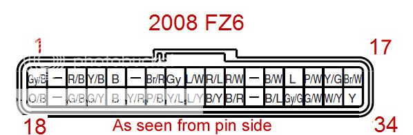
As best I can tell the CPU pin out (looking into the the CPU connector), is left to right bottom row is 1 -> 17
The US FSM shows no connection to Pin 2 and pin 6 goes to a wire designated as "D" (Pin #6 wire colors Y/R) which connects to nothing on our bikes.

Of course there are other ways to "count" the pin out, but that way has a whopping 2 points that line up with actual Pin outs called out in the FSM. I'm open if someone can show some proof as to which way is correct.
I was curious where 2 and 6 would go and what function they would have. I found nothing. Can someone from Europe post the PN of your ECM?
2013-08-12 Added Label drawing:
Reference the 2007 FSM for item descriptions to MATCH the ITEM numbers although most are self explanatory. ** Not responsible for errors **


JJD952