LED Panel & Arduino instrument cluster

markersniffen

Junior Member
Joined
May 27, 2011
Messages
66
Reaction score
4
Points
0
Location
Rochester NY
www.marksniffen.com
With a long overdue streetfighter conversion starting to take shape in my head, I had idea to create a custom instrument cluster using an Arduino and an LED Panel.

I wanted something that would stand out, that would allow me to design a simple, pretty, and effective way of showing the critical (to me) info that I wanted well riding. (Speed, RPM, Fuel, turn signals, highbeam, neutral, and the evil orange "something's broken" light)

I liked the idea of a low resolution LED display, so I decided on using two 8x8 RGB LED panels, creating an effective resolution of 16x8.

I started with designing the look digitally, I attached one of the renders to this post. I have an Arduino UNO that is running the show, however I may look into the nano because it is smaller. The LED panels I purchased are ridiculously bright, and are very easy to control via an Arduino:
Adafruit NeoPixel NeoMatrix 8x8 - 64 RGB LED Pixel Matrix ID: 1487 - $34.95 : Adafruit Industries, Unique & fun DIY electronics and kits

I've written most of the code to display the info, the biggest task for me will be getting the data from the bike into the Arduino. Having very little experience with circuits and electronics, I have a couple questions, and I'm hoping there's an electrical engineer around who might be able to help.

For starters, I gleaned a lot of knowledge from [MENTION=3100]Se7enLC[/MENTION] 's similar project:
http://www.600riders.com/forum/fz6-mods/46298-custom-dash-display-panel-arduino-lcd.html
Reading through his thread I learned a lot, and I learned that I need to learn a lot. :eek:

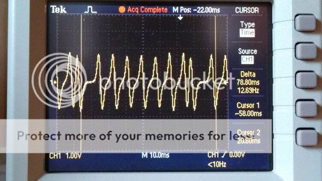
So for today, we'll just start with the RPM. The goal is to 'read' the crank position sensor (CPS) and feed that into the Arduino. I borrowed an oscilloscope from work and lifted the tank and starting testing things. (I also spent way too long trying to make sense of the electrial diagram from the service manual)

According to my testing, the CPS spits out an ac sine wave, of which I captured via the o-scope at two RPMs: ~1400 and ~5000 (see attached images)
To make this work, the wave needs to be squared (make it readable by Arduino), the negative voltages removed (protect Arduino), and the positive voltage regulated (down to 5v, also to protect Arduino).
From what I understand, resistors can bring the voltage down, zener diode will restrict the flow and remove negative voltages, and a schmitt trigger will square the wave. (Thanks Se7enLC!)

The one thing I'm unsure of is regarding the fact that the voltage changes as the RPM changes. If I am reading the scope correctly, at ~1400 RPM the voltage peaks around 12v...at ~5000 RPM the voltage peaks around 30v...? First off, 30v seems high...keep in mind I have a very primitive understanding of electrical theory...anyway my point is that if I do the math and set up a resistor divider network (thank you wikipedia) for the 12v signal, the math will be off for the 30v signal...and who knows what voltage comes out at 14,000 RPM, right? My best guess is that I should set up the resistors for the highest voltage, but this means the peak voltage for the lower RPM's will be very low, which makes me wonder if the Schmitt trigger will actually pick up those waves. Am I confusing anyone yet? Because I am confusing myself.... :rolleyes:

Here's the parts I have:

Zener Diode - https://www.jameco.com/webapp/wcs/s...storeId=10001&catalogId=10001&productId=36097
Schmitt Trigger - https://www.jameco.com/webapp/wcs/s...toreId=10001&catalogId=10001&productId=283792

I also attached a simple schematic I drew up for interpreting a 5v square wave AND a 12v AC wave...any glaring issues? My other question was regarding ground...I assume I would be grounding to the bike and not back into the Arduino for these circuits?

Thanks in advance! :rockon:
 

srghyc

Junior Member
Joined
Apr 10, 2013
Messages
45
Reaction score
0
Points
0
Location
St. Louis, Missouri
Visit site
Ah, turning mechanical motion into digital information. This is a great all around project. I'm excited to see what you come up with and more importantly: HOW.
 

patrickb37

Junior Member
Joined
Oct 7, 2011
Messages
102
Reaction score
0
Points
0
Location
Golden, CO
Visit site
Resident EE here. The IC link you posted is not a Schmitt Trigger, it's just a digital logic inverter circuit. If you want to build a Schmitt Trigger, you'll need to use op amps or comparator ICs.

Also, converting your input signal to all-positive can be done with something like a full-wave bridge rectifier circuit. You could implement it with standard 1N4148 diodes or just buy an integrated part (they have them on Digikey).
 

markersniffen

Junior Member
Joined
May 27, 2011
Messages
66
Reaction score
4
Points
0
Location
Rochester NY
www.marksniffen.com
Thanks for the reply --

A comparator would seem to produce a more accurate/stable signal for the Arduino than simply feeding the positive spectrum of a sine wave into the arduino.

I've been doing more research and according to wikipedia:
"A comparator normally changes its output state when the voltage between its inputs crosses through approximately zero volts."

This seems to answer my long winded question about the variable voltage....the since the 'switch' occurs at zero volts, the variance in peak voltage shouldn't matter...

...which means I need to send the comparator the sine wave without cutting out the negative voltages. I could put a diode in after the comparator just to protect the arduino from stray negative voltages...?

Signal from CPS > resistor network > comparator > diode(maybe) > arduino
 

FinalImpact

2 Da Street, Knobs R Gone
Site Supporter
Joined
Mar 16, 2011
Messages
11,137
Reaction score
184
Points
63
Location
USA, OR
Visit site
I don't have time for a detailed reply but I'm very interested. Take a look at this (( http://www.600riders.com/forum/fz6-...imppact-winter-project-playing-w-trigger.html )) and you might do a search for "JJD952 Electrical" and see what I've flagged along the way as something I wanted to find later. There are several threads on cluster issues and if I had to guess, I think they did a I2C communication as its a single wire to the gauge for

Tach, Speed, Error codes, and basic digital data but not the LEDs...

I can help you make sense of the schematic. That Hall effect sensor's voltage has considerable gain with RPM. I could not harness it easily and gave up trying to capture the marker....
TriggerIMG_20130928_112849_460_zps0fa750dc.jpg


Subscribed! JJD952 Electrical
 

ChanceCoats123

Junior Member
Joined
May 16, 2014
Messages
668
Reaction score
2
Points
0
Location
Chicago Suburbs
Visit site
I can't call myself a full fledged electrical engineer, but I am a second year computer engineer with my basics of computing (and electrical circuits) under my belt. :thumbup:

With regards to your most recent post about putting a diode after the comparator, I don't think it would be necessary:

Typically, comparators look at two voltages (one is the input and the other is a threshold set by you) and give a logical high (typically 5 volts) to one of three pins. The three pins are usually named something like A>B, A=B and A<B.

So my idea for an oscillating signal like the AC wave from the CPS, is that you could set the threshold voltage to 0V (or as close as the comparator allows) and hook the Arduino to the "equals" pin on the comparator. This way, every time the voltage from the CPS flips sign, the equals pin will go high.

The only problem that I can think of off the top of my head is that I don't know quite how the CPS works. If a single revolution of the crank corresponds to a complete sine curve, then the above connection should work pretty well.

On the other hand, if one turn of the crank corresponds to something other than a complete sine wave, then a different approach will be needed.


But with all of that said, you should just be able to take one of the output pins from the comparator and wire directly to the appropriate input on the Arduino. This is because the comparator (typically transistor-transistor logic), are already functioning with 5V power and a GND. So the output would already be something like 4.9 volts depending upon the drop in the comparator.
 

chunkygoat

Member
Joined
Oct 26, 2008
Messages
792
Reaction score
11
Points
18
Location
Pennsylvania
Visit site
Without going too far into depth, I think you're going to face the question:

Analogue or Digital

I think there are countless ways to achieve what you're looking for. Off the bat, I think the voltage you're looking for is not the easiest key to this puzzle. I think it is the frequency of the voltage that you are going to analyze. This may prove easier to work with.

View attachment 53951

I am going to precursor this with: I don't know if this will actually work. I have never tried this, but these are my initial thoughts.

I would think, being an embedded guru, that the idea of counters would appeal to you. You can buy yourself a cheap digital counter IC. Using pullup resistors, the AC wave would increment the counter for every pass of the CPS. You can use a regulator to regulate the voltage of the sensor down to 5v for the input of the counter. The counter would then output a binary representation of the counter's held value. With some simple math functions, and by tying the clocks together of the Arduino and counter, you would know the speed by which your data is coming in.

If you can use a serial out counter, you can easily use the Rx and Tx pins of the Arduino to serial in the data from the counter. From there you can write a script to correlate the count of counter to the speed of the clock and deduce your RPMs accordingly.

Depending on how savy you are with the Arduino IDE, you may want to try your chances with a lookup table, or maybe just mapping the value of the counter to a value of RPMs.


But like I said, I am not sure if this would actually work. I think there can be numerous ways to achieve this though- its just a matter of how you'd like to do it. Are you a digital guy (which is sounds you may be), or are you old fashion analogue. I'd go digital with it and use an 8 bit counter - cheap and easy. You could definitely also use other TTL logic gates too if you'd like (OR gates, And gates, etc.).

Just my thoughts there, hope this helps.
 
Last edited:

markersniffen

Junior Member
Joined
May 27, 2011
Messages
66
Reaction score
4
Points
0
Location
Rochester NY
www.marksniffen.com
Excellent ideas and info!

chunkygoat, the digital counter IC definitely intrigues me! I like the idea of leaving the counting to that IC, it make the code simpler for keeping track of the RPM. I am a digital guy and understand digital much better than analog, but at the same time I would like to learn how to solve the analog way. That being said, the counter makes sense to me, which means it would be easier to do. Time to research!

From what I understand of the CPS, each sine curve is created as one of the 8 or 9 teeth of the gear attached to the engine pass the sensor, so one revolution would be frequency / 8 or 9. Once I get a functioning circuit that doesn't fry anything, I am pretty confident I can calibrate it.

Also, one thing I've been thinking of: should I be concerned about tapping right into the CPS and other electrical lines with regards to affecting how the bike operates?
 

FinalImpact

2 Da Street, Knobs R Gone
Site Supporter
Joined
Mar 16, 2011
Messages
11,137
Reaction score
184
Points
63
Location
USA, OR
Visit site
I don't have time for a detailed reply but I'm very interested. Take a look at this (( http://www.600riders.com/forum/fz6-...imppact-winter-project-playing-w-trigger.html )) and you might do a search for "JJD952 Electrical" and see what I've flagged along the way as something I wanted to find later. There are several threads on cluster issues and if I had to guess, I think they did a I2C communication as its a single wire to the gauge for

Tach, Speed, Error codes, and basic digital data but not the LEDs...

I can help you make sense of the schematic. That Hall effect sensor's voltage has considerable gain with RPM. I could not harness it easily and gave up trying to capture the marker....
TriggerIMG_20130928_112849_460_zps0fa750dc.jpg


Subscribed! JJD952 Electrical

Did anyone look at this? The CPS has upwards of 50v PP at high rpm. The trigger wheel is not evenly spaced. See here... http://www.600riders.com/forum/fz6-...imppact-winter-project-playing-w-trigger.html

So if you dont need that signal to run the engine forget abour it and use the injector or ignition output.
 

pulsar2

Junior Member
Elite Member
Joined
Apr 1, 2013
Messages
254
Reaction score
1
Points
0
Location
New Albany,Ohio USA
Visit site
When I created my first digital dashboard for my motorcycle was converting the analog signal to digital using a opto-coupler/opto-isolator. A good size resistor will manage the voltage and the trigger (LED input) input needs really low current to switch it.
Once we got the square wave, we just fed it into one of the external timer/clock input of a microcontroller and setup 1sec interrupts to read the external clock/counter value. This gave us the RPM.

After this, I did try to get into creating a custom CDI for my single cylinder 150cc motorcycle, but could not get the firing right without an oscilloscope . I remember trying to check if the sparks are getting generated and my friend casually walking over and cranking the engine for a second or two. Damn thing zapped like 20 times before he stopped and he didn't realize why I was shaking all of a sudden.
 

markersniffen

Junior Member
Joined
May 27, 2011
Messages
66
Reaction score
4
Points
0
Location
Rochester NY
www.marksniffen.com
I did notice, I haven't had a chance to read through the thread you posted in detail, but I figured if I am just counting the number of pulses over a period of time, the offset tooth on the trigger wheel wouldn't cause a huge issue.

The voltage on the other does seem like it could be a pain to deal with.
 

FinalImpact

2 Da Street, Knobs R Gone
Site Supporter
Joined
Mar 16, 2011
Messages
11,137
Reaction score
184
Points
63
Location
USA, OR
Visit site
When I created my first digital dashboard for my motorcycle was converting the analog signal to digital using a opto-coupler/opto-isolator. A good size resistor will manage the voltage and the trigger (LED input) input needs really low current to switch it.
Once we got the square wave, we just fed it into one of the external timer/clock input of a microcontroller and setup 1sec interrupts to read the external clock/counter value. This gave us the RPM.

^^ I could see that being OK for basic RPM reading, but not for fueling or spark. That is if I understood it correctly. Allot happens in 1 second especially on a engine w/14k range.

After this, I did try to get into creating a custom CDI for my single cylinder 150cc motorcycle, but could not get the firing right without an oscilloscope . I remember trying to check if the sparks are getting generated and my friend casually walking over and cranking the engine for a second or two. Damn thing zapped like 20 times before he stopped and he didn't realize why I was shaking all of a sudden.

I did notice, I haven't had a chance to read through the thread you posted in detail, but I figured if I am just counting the number of pulses over a period of time, the offset tooth on the trigger wheel wouldn't cause a huge issue.

The voltage on the other does seem like it could be a pain to deal with.

This is the trigger wheel the sensor is reading. I didn't have the means to spin it too 14K but at 5K it was already at 25V PP.
Trigger_S320_zpsdee3c0bd.jpg


You must keep in mind you can't load it down and impair the ECM's interpretation of the CPS signal.

IMO without detecting the camel hump on the trigger, you'll never know the actual rpm. I suppose you could IGNORE the hump and grab the injector signal(s) but it may or may not be advanced or retarded in relation to the Crank Sensor. It would offer reference for your timing needs.
The ignition is advanced and retarded based upon load (operating conditions) so its not a good candidate for a trigger.

The goal of that thread was to use that trigger wheel and build an ignition box so I could drop in 4 COPs and ditch the waste spark coils. The goal being able to program the ignition advance curve and wake this engine up.

EDIT: Forgot to add this:
52313d1394663685-07-fz6-cluster-not-working-img_20140312_134226_173-jpg


I'm guessing the communications to the instrument is propriety but it may be something standard.
 
Last edited:

markersniffen

Junior Member
Joined
May 27, 2011
Messages
66
Reaction score
4
Points
0
Location
Rochester NY
www.marksniffen.com
So I'm at the point where I need to start playing with circuits or I will end up researching things until the end of time. I'm going to take a stab at regulating the crazy CPS signal with a zener diode clipper circuit, then feed it into a 555 counter IC. I tested a clipper circuit with a 12v AC wall wart I had lying around, and it worked...which means it should theoretically work for the idling RPM.

The timer IC will effectively isolate the CPS signal from the Arduino, that would be the primary purpose of it. The fact that it would count for me makes the coding side of the process a bit simpler. Win-win!

Baby steps I say...even if this method doesn't work, I've learned a ton.

Also, here's a quick video of the LED panels in action...the data is just randomly generated by the Arduino. Speed is the numbers, the two red bars are RPM, the blue "corners" are highbeams, 4 green LED's in the center-ish are neutral, and the turn signal are obvious. As someone who works in video production, I apologize profusely for the shaky camera:

https://drive.google.com/file/d/0B_TErllkyzM4WmVxbktNdGwtZXM/edit?usp=sharing
 

markersniffen

Junior Member
Joined
May 27, 2011
Messages
66
Reaction score
4
Points
0
Location
Rochester NY
www.marksniffen.com
...since the digital counter IC should "flip" each binary switch when it detects the falling edge of a pulse, as long as each pulse is separate it shouldn't miss any....the two teeth that are really close seem concerning but if I'm reading the o-scope image correct each pulse seems to definitely be separate.

I used Microsoft Paint for the first time in a looong time to bring you the attached graphic...
 

chunkygoat

Member
Joined
Oct 26, 2008
Messages
792
Reaction score
11
Points
18
Location
Pennsylvania
Visit site
...since the digital counter IC should "flip" each binary switch when it detects the falling edge of a pulse, as long as each pulse is separate it shouldn't miss any....the two teeth that are really close seem concerning but if I'm reading the o-scope image correct each pulse seems to definitely be separate.

I used Microsoft Paint for the first time in a looong time to bring you the attached graphic...

I do not think this is necessarily true. As long as the input is riding at a high logic level when the clock ticks - the counter will increment.
 

markersniffen

Junior Member
Joined
May 27, 2011
Messages
66
Reaction score
4
Points
0
Location
Rochester NY
www.marksniffen.com
Hmmm...so if that is true, there is the possibility of the counter missing pulses OR triggering the counter more than once per pulse...depending on the speed of the counter IC?

I was learning via video, and the counter the guy was using a counter that he described would switch logic based on the input frequency, specifically when the signal went from high to low:
https://www.youtube.com/watch?v=q6seLjocWK8

Also wikipedia talks about the differences between Synchronous and Asynchronous (ripple) counters...Counter - Wikipedia, the free encyclopedia

Not sure if that refers to the difference we are talking about...?
 

markersniffen

Junior Member
Joined
May 27, 2011
Messages
66
Reaction score
4
Points
0
Location
Rochester NY
www.marksniffen.com
Hey all,

I was able to successfully get the CPS signal into my arduino! Blah It's not perfect, and I'm still working out some kinks...I attached an image of the circuit I used:

CPS signal > 50k resistor > zener clipping circuit > comparator-turned schmitt trigger with resistors...(waiting for the real Schmitt Trigger to arrive in mail) > Arduino interrupt pin.

The code right now increments a counter every time a pulse hits the interrupt pin of the Arduino. The program checks every second and notes the time and count, does some math, and spits out how many pulses it recorded in one second. I am getting ~280 pulses at idle (~1500rpm), which is not correct:

(280 pulses / 8 teeth) * 60 seconds = 2100 rpm....

what I should be getting:

(200 pulses / 8 teeth) * 60 = 1500.

I compared the actual output of the CPS with the output of my schmitt trigger on my oscilloscope, and they match. I have to determine whether or not my code is creating the variance or if the arduino is detecting false pulses. I'll try and actually get images of the scope next time!

The photo is me in progress of playing with the circuit...what you see there is not what I ended up with...

Also, if anyone is interested, I have a thread open on the arduino forums for more specific arduino help:
LED Motorcycle instrument cluster - getting RPM from crank position sensor - Arduino Forum
 

FinalImpact

2 Da Street, Knobs R Gone
Site Supporter
Joined
Mar 16, 2011
Messages
11,137
Reaction score
184
Points
63
Location
USA, OR
Visit site
As stated before allot happens in 1 second. So the new tach may not be accurate until you reduce that 1sec interval. It will give a ball park figure and likely be OK at a steady state RPM.

I know I mentioned the pickup was a Hall, that is incorrect. Its a AC magnetic pickup coil hence the reason you see the voltage climb with RPM. Again, be prepared that it may exceed 50 volts PP as your reach higher RPM...

Potential Solution:
http://www.ti.com/lit/ds/symlink/lm1815.pdf
LM1815MX/NOPB Texas Instruments | 296-35392-6-ND | DigiKey $$4.00$$

Then scroll down about 2/3 of the way here: MS1/Extra Ignition Hardware Manual and/or search for "VR input Sensor wiring for a V2.2 PCB"

LM1815 Adaptive Variable Reluctance Sensor Amplifier
FEATURES

• Adaptive Hysteresis
• Single Supply Operation
• Ground Referenced Input
• True Zero Crossing Timing Reference
• Operates from 2V to 12V Supply Voltage
• Handles Inputs from 100 mVP-P to over 120VP-P with External Resistor
• CMOS Compatible Logic

APPLICATIONS
• Position Sensing with Notched Wheels
• Zero Crossing Switch
• Motor Speed Control
• Tachometer
• Engine Testing

DESCRIPTION
The LM1815 is an adaptive sense amplifier and default gating circuit for motor control applications. The sense amplifier provides a one-shot pulse output whose leading edge coincides with the negative- going zero crossing of a ground referenced input signal such as from a variable reluctance magnetic pick-up coil.
In normal operation, this timing reference signal is processed (delayed) externally and returned to the LM1815. A Logic input is then able to select either the timing reference or the processed signal for transmission to the output driver stage.

The adaptive sense amplifier operates with a positive going threshold which is derived by peak detecting the incoming signal and dividing this down. Thus the input hysteresis varies with input signal amplitude. This enables the circuit to sense in situations where the high speed noise is greater than the low speed signal amplitude. Minimum input signal is 150mVP-P.
 
Last edited:

FinalImpact

2 Da Street, Knobs R Gone
Site Supporter
Joined
Mar 16, 2011
Messages
11,137
Reaction score
184
Points
63
Location
USA, OR
Visit site
52313d1394663685-07-fz6-cluster-not-working-img_20140312_134226_173-jpg


I'm guessing the communications to the instrument is propriety but it may be something standard.

That 24 pin ic = 5-Channel Gauge Driver with Serial Link
Apache Tomcat/6.0.26 - Error report

If you look at how it communicates you may be able to interpret what the ECM is saying and use the data directly from the serial data link to the display. The downside is the data likely comes from the that 100 QFP which doesn't pop up under findchips.com.

However there is this thread that came back to life - Lets just say people have been creative! Yamaha FI Diagnostics tool - ECU hacking

Motorcycle black box. Part 1 : data acquisition with Arduino Mega. | Iwasz
 
Top