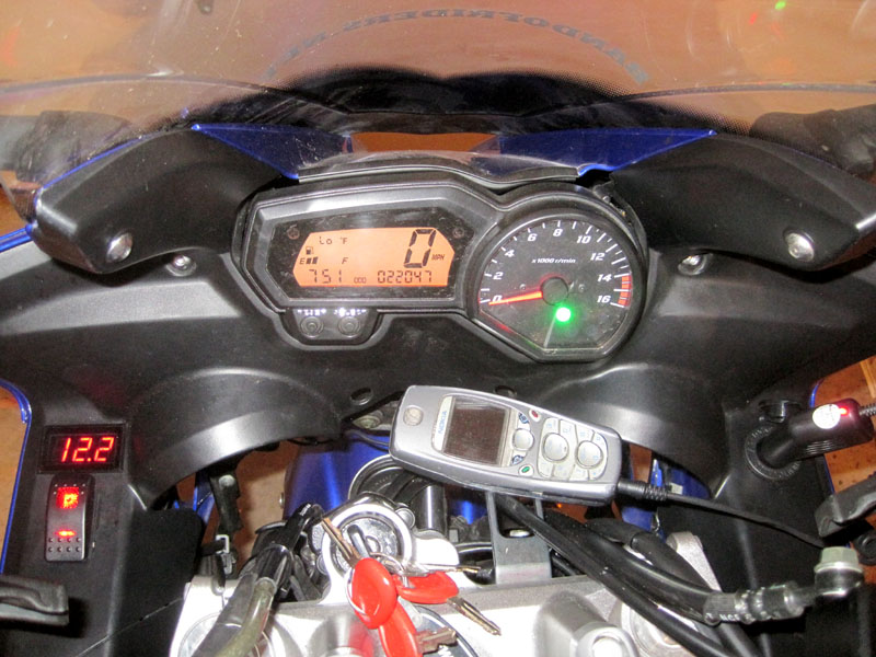
Got this little project all wrapped up and took a bunch of pictures. I'm pretty happy with the way it turned out. I spent quite a bit of time planning out my wiring and the schematics.
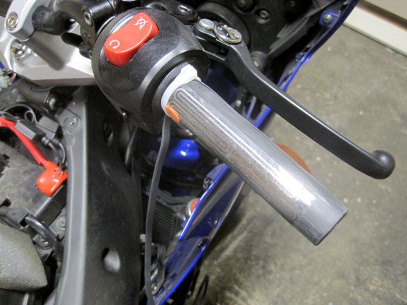
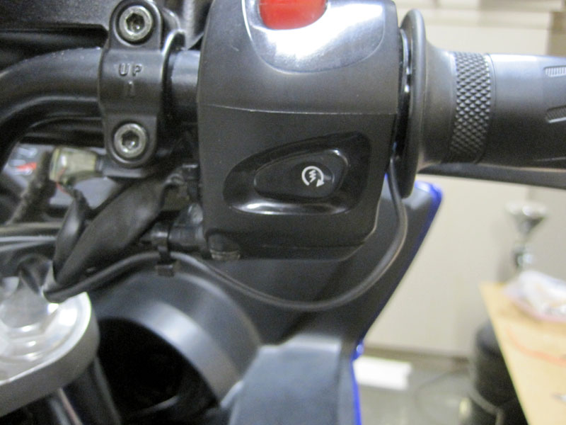
After powdercoating the handlebar, first step was putting on the grips. Clutch side got about 4 wraps of Kapton tape first (hindsight I would've put a couple more, since the throttle side is a little warmer on high). I put zip-ties around the wires where they leave the heater as a strain relief. (After this pic, I switched it to a black ziptie, as it hides a little better and the head was a little smaller than this one.)
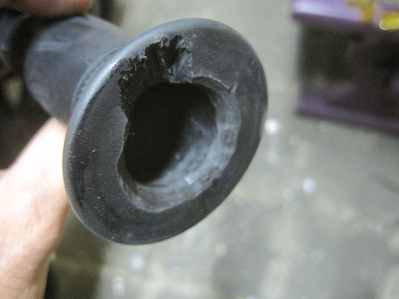
Shaved off a bit of each grip to allow for the ziptie
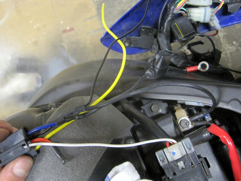
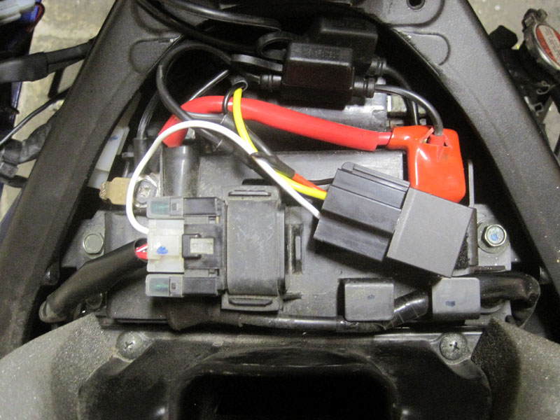
Relay Wiring. I bought a fused battery tender lead for $5 and cut off the SAE connector. On the relay connector, the red lead is the NC outlet (not used) cut and insulated. White is the switching source. Blue is connected to the positive lead. The ground side of the battery terminal lead splices into the black relay connector lead. Yellow is the switched power out.
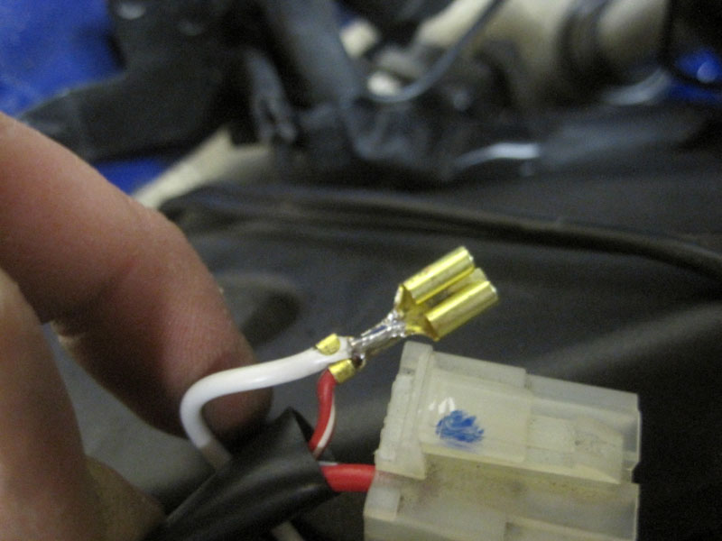
White lead soldered to the crimped connector on the starter relay.
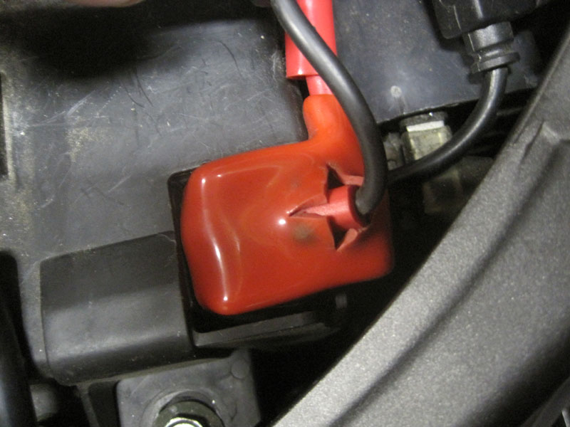
2 sets of ring terminals on the battery now, new plus my existing battery tender lead.
Relay velcroed to the top of the battery box, everything tucked in nicely.
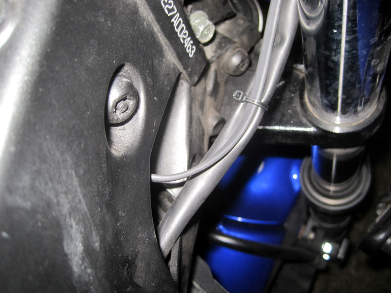
Now, how should I run the wires to the grips neatly? Leaving a little extra on the throttle side to allow for WOT with no interference, I followed the wire loom down...
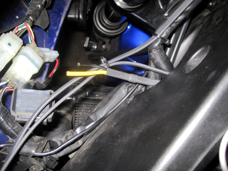
...and into the frame, in front of the battery...
...and out the left side, where it met up with the clutch side wires, and the yellow (switched power) and black (ground) wires from the relay.
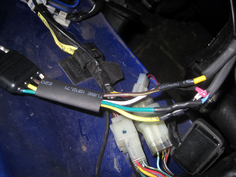
I used a trailer wiring connector to connect all the bike-side wires to my inner-fairing wires. The grounds (red from the grips, black from the relay) get tied to the white wire (exposed pin), the yellow power wire connected to the brown, and the whites and blues (high/low from the grips) connected to the green and yellow.
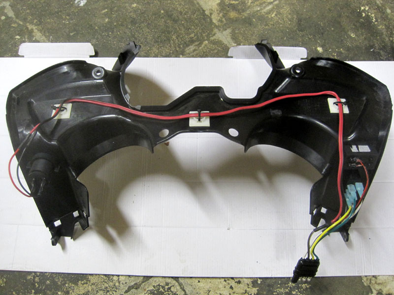
Back side of the inner fairing. Voltmeter and SPDT switch mounted on the left side, 12v outlet mounted on the right. The brown power wire splits to the outlet, the voltmeter, and the center pin on the switch. Ground wire splits to outlet, voltmeter, and the ground pin on the switch (LED switch). Green and yellow to the high and low sides of the switch. So with this setup, I can just unplug the trailer connector and remove the inner fairing.
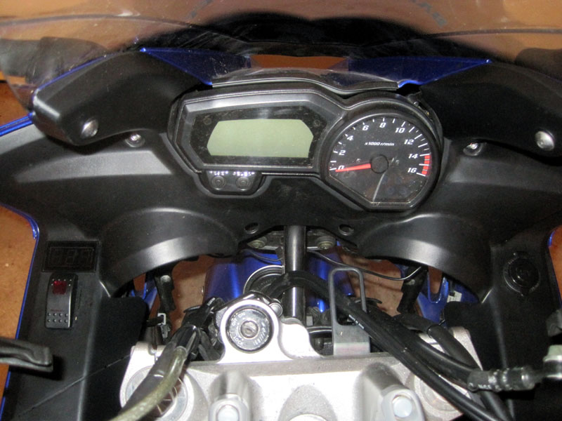
Everything back assembled, looks pretty clean.
Everything powered up, voltmeter working, phone charging, grips heating!
Here's the only snafu I ran into that drove me nuts for about an hour. I used
this type of switch for the grips. It's got a big light for high, and a smaller light for low. Cool, in theory. But, with the way the Symtecs heaters are wired, it's not two separate circuits for high and low. The low circuit uses the high circuit, plus an additional length to increase the resistance. This results in the low side of the switch seeing 12v when the switch is on high, and the high side of the switch seeing ~6.5v when switched on low. Hence both LED's illuminating on both high and low.
To fix this, I would either need to open up the switch and install a couple small diodes between the switched poles and the LED's... or put diodes capable of handling the full 3+ amps on the green/yellow wires coming from the switch. But a 4amp diode would drop the voltage going to the grips by about 0.8 volts, making them slightly cooler, so I'm not sure I want to do that just yet.