**************************
DIAGNOSTIC MODE
**************************
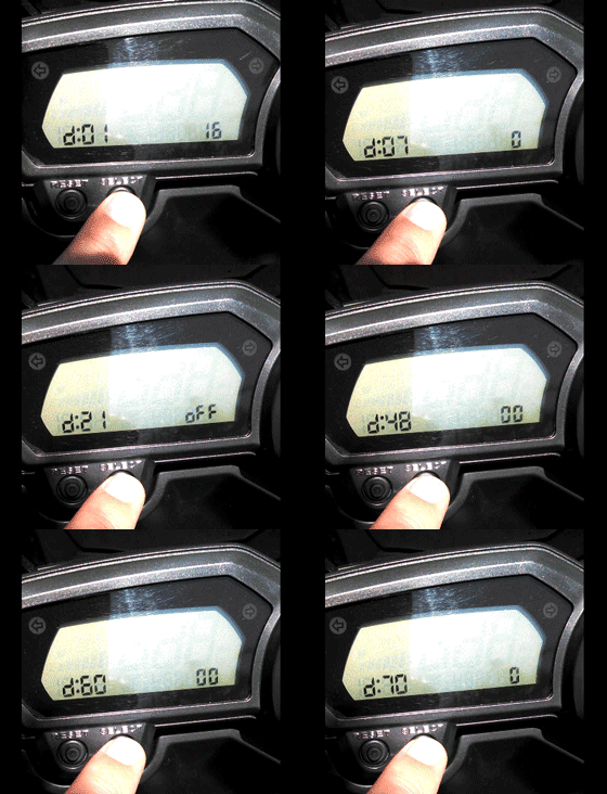
The ECM has the ability to verify some of the sensors and switches on the vehicle. When placed into diagnostic mode it can also display inactive error codes and some history as well as test both the ignition coils and the fuel injectors. For most of these tests, the FSM instruction the user to disconnect the Fuel Pump power (Green connector under the fuel tank).
Setting the diagnostic mode S1 Models:
1. Turn the main switch to “OFF” and set the engine stop switch to “STOP”.
2. Disconnect the wire harness coupler from the fuel pump (GREEN connector).
3. Simultaneously press and hold the “SELECT” and “RESET” buttons, turn the main switch to “ON”, and continue to press the buttons
for 8 seconds or more.
• All displays on the meter disappear except the clock and trip-meter displays.
• “dIAG” appears on the LCD meter.
4. Press the “SELECT” button to select the C0 adjustment mode “C0” or the diagnostic mode “dIAG”. US bikes will only display "dIAG", unless a jumper wire is grounding a pin in the harness to enable C0/C1 fuel trim adjustments.
5. After selecting “dIAG”, simultaneously press the “SELECT” and “RESET” buttons for 2 seconds or more to execute the selection.
6. Select the diagnostic code number that applies to the item that was verified with the fault code number by pressing the “SELECT” and “RESET” buttons.
7. The diagnostic code number appears on the LCD meter (01-70).
• To decrease the selected diagnostic code number, press the “RESET” button. Press the “RESET” button for 1 second or longer to automatically decrease the diagnostic code numbers.
• To increase the selected diagnostic code number, press the “SELECT” button. Press the “SELECT” button for 1 second or longer to automatically increase the diagnostic code.
Setting the diagnostic mode S2 Models:
1. Turn the main switch to “OFF” and set the engine stop switch to “STOP”.
2. Disconnect the wire harness coupler from the fuel pump (GREEN connector).
3. Simultaneously press and hold the “SELECT” and “RESET” buttons, turn the main switch to “ON”, and continue to press the buttons
for 8 seconds or more.
• All displays on the meter disappear except the clock and tripmeter displays.
• “dIAG” appears on the LCD meter.
4. Press the “SELECT” button to select the C0 adjustment mode “C0” or the diagnostic mode “dIAG”. US bikes will only display "dIAG", unless a jumper wire is grounding a pin in the harness to enable C0/C1 fuel trim adjustments.
5. After selecting “dIAG”, simultaneously press the “SELECT” and “RESET” buttons for 2 seconds or more to execute the selection.
6. Set the engine stop switch to “OFF”.
7. Select the diagnostic code number that applies to the item that was verified with the fault code number by pressing the “SELECT” and “RESET” buttons.
NOTE:
The diagnostic code number appears on the clock LCD (01–70).
• To decrease the selected diagnostic code number, press the “RESET” button. Press the “RESET” button for 1 second or longer to automatically decrease the diagnostic code numbers.
• To increase the selected diagnostic code number, press the “SELECT” button. Press the “SELECT” button for 1 second or longer to automatically increase the diagnostic code numbers.
8. Verify the operation of the sensor or actuator.
• Sensor operation
The data representing the operating conditions of the sensor appears on the trip LCD.
• Actuator operation
Set the engine stop switch to “RUN” to operate the actuator.
NOTE:
If the engine stop switch is set to “RUN”, set it to “OFF”, and then set it to “RUN” again.
9. Turn the main switch to “OFF” to cancel the diagnostic mode.
S2 In Diagnostic Mode:
**************************
SYSTEMS that can be Verified:
**************************
To activate, turn Engine Run switch from OFF to ON while mode is selected.
01: Throttle position sensor (throttle angle)
30: Ignition coil #1, #4
31: Ignition coil #2, #3
36: Injector #1, #4
37: Injector #2, #3
48: AI system solenoid
51: Radiator fan motor relay is activated every 5 seconds.
52: Headlight relay is activated every 5 seconds (2 seconds ON, 3 seconds OFF) - 2003+ model only.
**************************
Diagnostic code table
**************************
NOTE: Where the following "•" is present, this data may not apply to all vehicles. In fact it looks like it applies to the R6 as it has 4 coils and coil ID. FI
Here's many of the Yamaha Fault Codes:
11 • No normal signals are received from the cylinder identification sensor when the engine is started or while the vehicle is being driven.
12 - No normal signals are received from the crankshaft position sensor.
13 - Intake air pressure sensor: open or short circuit detected.
14 - Intake air pressure sensor: hose system malfunction (clogged or detached hose.)
15 - Throttle position sensor: open or short circuit detected. Throttle position sensor (for throttle valves) coupler connection is loose.
19 - Open circuit is detected in the input lead from the sidestand switch to the ECU.
20 • When the main switch is turned to "ON", the atmospheric pressure sensor voltage and intake air pressure sensor voltage differ greatly.
21 - Coolant temperature sensor: open or short circuit detected.
22 - Air temperature sensor: open or short circuit detected.
23 • Atmospheric pressure sensor: open or short circuit detected.
24 - No normal signal is received from the o2 sensor.
30 - Latch up detected. No normal signal is received from the lean angle sensor.
33 - Malfunction detected in the primary wire of the ignition coil (#1 and #4). FZ6
34 - Malfunction detected in the primary wire of the ignition coil (#2 and #3). FZ6
35 • Open circuit detected in the primary lead of the cylinder #3 ignition coil. R6
36 • Open circuit detected in the primary lead of the cylinder #4 ignition coil. R6
39 • Open ciruit detected in a primary injector. R6
40 • Open circuit detected in a secondary injector. R6
41 - Lean angle sensor: open or short circuit detected.
42 - No normal signals are received from the speed sensor. Open or short circuit detected in the Neutral switch.
43 - The ECU is unable to monitor the battery voltage (an open circuit in the line to the ECU). Power supply to the injectors and the fuel pump is not normal.
44 - An error is detected while reading or writing on EEPROM (C0 adjustment value).
46 - Power supply to the fuel injection system is not normal.
50 • Faulty ECU memory. (When this malfunction is detected in the ECU, the fault code number might not appear on the meter.)
59 • Throttle position sensor (for throttle cable pulley): open or short circuit detected. Throttle position sensor (for throttle cable pulley) coupler connection is loose.
60 • Throttle servo motor: open or short circuit detected. Defective throttle servo motor. Malfunction in ECU (servo motor driving system).
Er-1 - No signals are received from the ECU.
Er-2 - No signals are received from the ECU within the specified duration.
Er-3 - Data from the ECU cannot be received correctly.
Er-4 - Non-registered data has been received from the meter.
Sensor operation table:
01 : Throttle angle Fully closed position 15–17, Throttle fully opened position 97-100
02 • Atmospheric pressure given in mmHg (normal is 760 - average weather)
03 : Differential pressure between air and intake pipe
05 : Air intake temperature (in Celcius)
06 : Cooling liquid temperature (in Celcius)
07 : Absolute speed (must be 000 in wheel stopped). Check with rear wheel (0-999).
08 : Lean angle safety switch control - must be from 0.4-1.4 (upright) to 3.8-4.2 (horizontal). DISMOUT THE SWITCH FOR CHECKING !!!
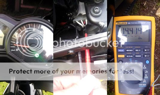
09 : Battery voltage - should track actual battery voltage, use a DMM to verify.
20 : Side stand switch - displays ON or OFF. Retracted = ON, Extended = OFF
21 : Neutral gear switch - displays ON or OFF. Neutral = ON, In Gear = OFF
ECU memory check:
60: EEPROM fault code display. No Fault = 00, 01 - 02 Fault detection cylinder. (01: #1 and #4 // 02: #2 and #3)
61 : Error Code memory log - Displays 00 if no error code in memory, displays the Error Code if any (11 to 50). Display changes every two seconds if more than one Error Code in memory, then starting at the LOWEST CODE FIRST and goes up if others exist .
62 : Malfunction history code
erasure. 00 = No history, 01- 17 = History exists. To clear the memory, switch the Engine Run Switch to ON position (no backup).
70 : Control number, display from 0 to 255
Following ERROR codes DO NOT allow engine to run:
12-19-30-41-50 and Er-1 to Er-4
Error code 11 allow engine to continue running only if fault appears after engine start.
Following ERROR codes DO allow engine to run but need immediate check because
default values are taken by the ECU: 13-14-15-16-21-22-24-33-34-42-43-44-46