Regards my friends ,
I just finished the specific conversion. The conversion actually needs space and time idd, but I will add patience because apart from the fact that most of the conversion is follow the steps whith a little research Combining manuals from the kit, forums with lighting and natural forums of this motorcycle , there are some points which are improvisation ( eg application of LED rings in shrouds and cable management on the bike ) .
The procedure is as follows :
A) Remove puss
1 ) Remove the A, B and C panels ( see manual Engine ) . 2 , 2 and 6 screws Alen respectively .
2 ) Remove the mirror . 4X No.10 nuts
3 ) Remove gelatin . 6X plastic screws .
4 ) Disconnect the two plugs left
5) Disconnect the connector of the display. If you do not succeed are three screws + 1 Alen ground in order to come out with the puss .
6 ) Pull the puss .
http://imageshack.us/a/img35/1037/7gff.jpg
http://imageshack.us/a/img843/4245/85kv.jpg
B ) Remove the lens of the puss . 5 screws
1 ) Remove the circular tire lamps
2 ) Remove the protective clip of lamps ( 1 +1 bolts )
3 ) Remove the H4 (left) and H7 (right) lamps .
4 ) Remove the two lamp post top left and top right .
http://imageshack.us/a/img51/3033/djhy.jpg
C) Open Headlight Housings
1 ) Turn on the oven at 100 , does not need more if the go - lens by lens is the best
2) Place the lens in the oven for 7 minutes ( do not close the thermostat ) .
3) With gloves and a screwdriver you first open the clips and then with some angle lantern , will open very easily and only with hands .
4) Remove as much glue as you with the screwdriver as you will put fresh later .
5) Repeat from 1 to 4 for the other lens.
http://imageshack.us/a/img31/1298/u16u.jpg
D) Preparation of shrouds
1 ) Whet small ring that each shroud has on top of them, so the LED rings apply smoothly. Calculate the cable to pass through one of the bottom (style vents ) gaps . The up and down of the shrouds you will know by the holes for the screws of projectors at their rear .
2) If you intend to apply the LED rings above shrouds with wires and not high-temp glue then this is where you pierce the shrouds with 1mm drill . Three holes in a triangle shape all around the shroud will be enough . At this point to say that the recommended method is wire because of the combination of temperature and turbulence . I personally did not get to find anywhere tie wire less than 1mm. I only had the option of a bouzouki string. However, the string is " naughty " and difficult bondage and so i fled to the high-temp glue solution.
http://imageshack.us/a/img6/6361/4iwg.jpg
http://imageshack.us/a/img560/8675/xqwx.jpg
http://imageshack.us/a/img854/8008/3ghf.jpg
E) Painting reflectors and shrouds
1 ) Thoroughly clean the reflectors and shrouds.
2 ) Spray 1 coat of primer for plastic
3 ) Spray 2 coats of Matt black with a one hour break between the two layers.
http://imageshack.us/a/img36/7882/eg6z.jpg
F) Placement of the projectors at headlight housing
1 ) Screw the projectors in shrouds. 4 screws for each.
2 ) Unscrew the bulb holders of each projector and the big nut.
2) For the H4 light ( left ) take the big silicon washer, place it behind the projector and place it onto the reflector by passing throught the hole the solenoid and LED cables .
3 ) We come from the back of the headlight and put the H4 metal adapter and then screw well by pressing from the front (the shroud) one of the nuts loosened in step 2 .
4 ) Repeat for the other projector the steps above, just use the little silicon washer and the metal adapter for H7 .
see manual of the projector by the Companys' web site to know what is every part for)
http://imageshack.us/a/img703/8799/xmj4.jpg
http://imageshack.us/a/img5/1166/zpw8.jpg
G) Close Headlight Housings
1 ) Place the black glue provided onto thegroove that makes the back of the headlight . Little stretching will help to micrin thickness to avoid overflow of the glue which would prevent us to close the clips .
2 ) As we did at the opening, put the headlight housings in the oven at 100 constantly for 7 minutes and hold the top closing clips for one to two minutes by the time u remoove it from the oven.
3 ) repeat, for the other lens .
http://imageshack.us/a/img23/4365/1i34.jpg
http://imageshack.us/a/img801/8467/kbu4.jpg
H) Screwing lanterns in puss and wiring
1) Place the OEM wiring behind the lights . It will center itself if you put the body of the display connector between the lenses .
2) With 5 screws put housings on puss .
3 ) Screw the 3 screws on the bulb holders
4 ) Remove carefully H1 bulbs and clean with alcohol wipes included in the kit. Place them in recesses.
5) Pass the protective metalware clips on the supports of the lamps .
6 ) Put back the position lights and connect .
7) Cut a bit of the terminals of LED rings and put them onto the position lamps plugs. It's kind unofficial way but if you are sure about the stability i beleive it is much more practical than the cut and jumper of the wires, note that there is not much room there. Unless you manage to find power supply from the battery or the main plug left.
8) At this point we get the wiring harness of the kit and connect according to the tags . We have 2 ballasts and central Motocontrol. Connect the Motocontrol with the H4 connector, with the ballasts and with the solenoids plugs for the high beam , which we make ourselves. The ballasts should be connected on the plugs of the H1 bulbs.
(At this point I was lacking knowledge, i had in mind that H4 adapter will give me both high and low beam :banghead: and so i isolated the H7 wires by tiring them up. So eventually everything works well except my low beam . This is because the wire harness of the Kit comes only with H4 adapter on the Motocontrol. My question is, whenever i reopen the bike where should i connect the H7 (low beam) OEM wiring?! I suggest i have to take the black with green stripes cable (low Beam-H7) and jumper it to 1 of the 3 wires of the H4 plug ( |_| White, blue or Brown)?! would that work?
9)!! If and only if you figure out what to do with the low beam wiring go on from here!! Apply the ballasts with double sided tape on the sides and the Motocontroll under a headlight housing,finally tuck the wires by tiring them up. I circled the ballasts with rubber and tire up for more protection .
http://imageshack.us/a/img844/7883/31w5.jpg
http://imageshack.us/a/img716/7025/r807.jpg
http://imageshack.us/a/img4/4039/zvpo.jpg
http://imageshack.us/a/img823/2157/xj8c.jpg
I) Replacing puss on the bike
1 ) Push and screw the puss by centering the two holes in the center frame.
2 ) Screw the dial and link connector and grounding.
3 ) Connect the grounding of ballasts. I suggest the nuts that hold the metal piece where the bottom screws of A and B panels go. There, the ground is close to the ballast and the wire isnt bothered by the handlebar steering .
4 ) Connect the positive of the Motocontroll to the battery (No.10 nut). Pass it between the posts,under handlebar and through a hole that there is close on the tank opening on the side.
5) A final tidying of cables at this point would be good.
6 ) Screw the mirrors
7) Replacing the C, A and B panels.
8) Screw windshield .
http://imageshack.us/a/img31/2949/ldng.jpg
http://imageshack.us/a/img194/530/jas0.jpg
http://imageshack.us/a/img59/5008/xvoq.jpg
http://imageshack.us/a/img194/1390/68bo.jpg
Time spent: 6 hours and money spent 250 euro.
I hope this Post to help anyone who wants to deal with this conversion, however its my pleasure to share my experience , cause others have helped me in the first place : P
Finally, I hope to figure it out with my low beam connection . " Enlight me ": D



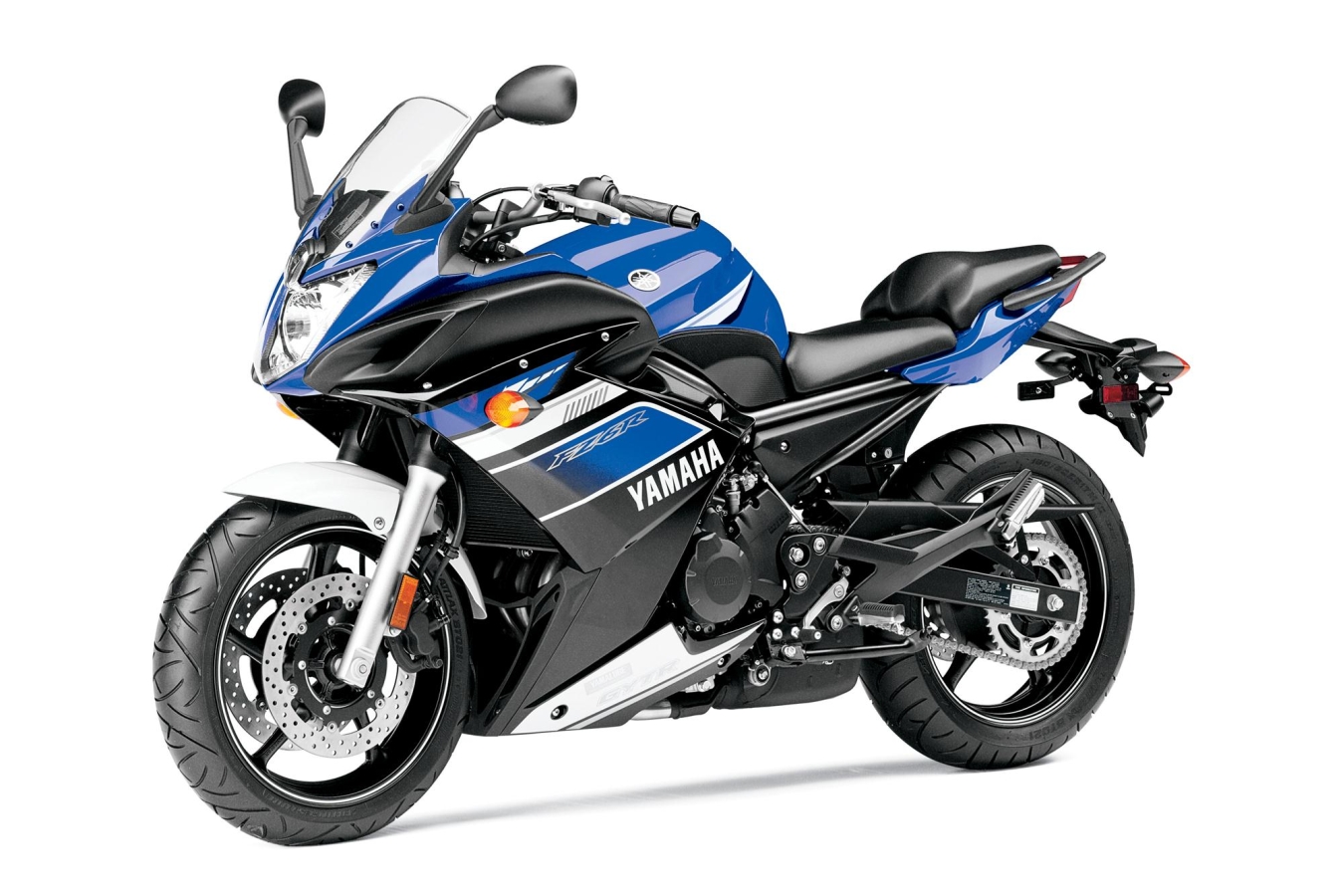

 .
. Im staying with the idea of wiring the H7 low beam positive wire with the #2 position of the H4 plug and hope it works