- Joined
- May 6, 2014
- Messages
- 2,518
- Reaction score
- 2,809
- Points
- 113
- Location
- Amongst the Twisty Roads
I installed a FZ6N headlight kit. This is both a very easy and very aggravating job - all at the same time. Let me explain.
The kit is complete - in fact it’s over complete because there is hardware that can’t possibly be used. What isn’t included in the kit are instructions. This is a common complaint with these Chinese kits. It’s not readily apparent how all of these pieces fit together. But once I had it all together I discovered a very important piece of the puzzle, the kit is meant to be installed as a completed assembly - not piecemeal. But in order to install it as a completed assembly you have to first install the bracket, make adjustments, remove the bracket and then assemble…several times.
Let’s discuss the bracket. I don’t think they used a jig when they welded this thing together. While everything is almost in the right place, it is horribly twisted resulting in a bracket that you have to fight with the entire time. I would spend some time to get the bracket in a state where it easily aligns with its three mounting points.
So here are the steps for installation:
Honestly, the home-brewed solution I have on my blue FZ was significantly easier to install (and I had to design it on the fly), took a fraction of the time, and looks unique. I wouldn’t use one of these kits again. It was a very unsatisfying job but it does have the OEM FZ6N look.
The kit is complete - in fact it’s over complete because there is hardware that can’t possibly be used. What isn’t included in the kit are instructions. This is a common complaint with these Chinese kits. It’s not readily apparent how all of these pieces fit together. But once I had it all together I discovered a very important piece of the puzzle, the kit is meant to be installed as a completed assembly - not piecemeal. But in order to install it as a completed assembly you have to first install the bracket, make adjustments, remove the bracket and then assemble…several times.
Let’s discuss the bracket. I don’t think they used a jig when they welded this thing together. While everything is almost in the right place, it is horribly twisted resulting in a bracket that you have to fight with the entire time. I would spend some time to get the bracket in a state where it easily aligns with its three mounting points.
So here are the steps for installation:
- Since the fairing bracket was removed you must install two bolts in the frame, replacing the ones that attached the fairing bracket to the frame. I think some of the unused hardware was intended for this purpose, but the bolts were way too short and no nuts were included. Perhaps they thought that one of the holes was threaded.
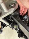
- Remove the horn bracket and the brake hose clamp on the lower triple clamp. Before removing the bracket you will need to bend the horn bracket down a few degrees so it clears the lower “U” bracket supplied with the kit which becomes the lower mounting point for the headlight bracket. You will also need to cut off the brake hose attachment point because you will reuse the horn bracket, but the brake hose mount interferes with the light unit. Remove the horn from the bracket so it doesn’t get damaged.
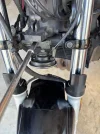
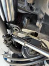
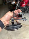
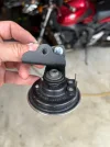
- Install the lower “U” bracket where the horn bracket was installed. Place the horn bracket behind the U bracket.
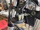
- Remove the bracket from the upper triple clamp that holds the throttle cable guide. Now is a good time to remove the throttle cables from the grip and the clutch cable from the lever.
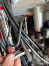
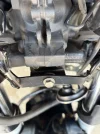
- Temporarily install the light & instrument bracket to the new lower bracket and the upper triple clamp location - just so you can see how this will attach later in the assembly. You will note that there is a spot for a third bolt location on the left hand side of the bracket. You will need to drill and tap (M6) a hole on the underside of the triple clamp for this bracket. “Where” you ask? Well that’s one of the frustrating things about this project, you won’t know until you have everything assembled on the bracket…but you will see a marked spot on the bottom of the upper clamp for this hole location…it looks like a filled hole. So now it’s time for assembly.
- Remove the bracket and bring to a workbench. Attach the light to the bracket placing the two outer plastic pieces on each side with the large holes for the turn signals at the top. Nothing will line-up, so twist the bracket as necessary to get the 4 M6 bolts started. The kit comes with rubber sleeves for the upper inner mounts. I didn’t like these, and instead used two rubber grommets and M6 bolts/washers to securely mount the light to the bracket. It’s easiest if you start with these before moving on to the 4 outside bolts. You may find that the tab at the bottom for the brake line mount interferes with the fitment of the light. Go ahead and bend it out of the way…because it doesn’t line up with the mount on the lower triple clamp anyway. I used a zip-tie to secure the brake line (stand-off method).
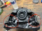
- With the light mounted you can install the instrument cluster to the bracket. None of these parts lined up for me, so I modified the mounting to work. I will likely add an additional lower bracket for added stability.
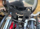
- Install the turn signals to the assembly. The turn signals do not come with connectors. You can crimp or solder them to the harness. For $20 (mostly shipping) I got OEM connectors from Eastern Beaver. The wiring on the directionals is generic; green is ground, blue is always on, and the white is the flashing turn signal. So the green goes to the black in the harness, the blue to the blue/red, and the white goes to either the chocolate (left/black connector) or dark green (right/gray).
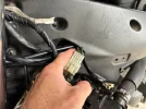
- You can’t add the new rear housing to the instrument cluster without the two instrument cluster connectors in place so you will now be moving the assembly to the bike. But before you do that, convert the H7 socket to an H4 by depinning the yellow/black wire from the one connector and adding it to the open spot on the other connector.
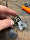
- Once again, attach the lower bracket and the upper t-clamp bolt. Push the other bracket to the rear of the t-clamp back by the ignition. Now you can mark the location to drill the new mounting location. You’ll need to once again remove the light assembly. You’ll also need to remove the top triple clamp because there is not enough access to drill & tap it while installed on the bike. When putting the upper t-clamp back on the bike the steering stem nut gets torqued to 80 ft-lbs, the pinch bolts are 22 ft-lbs and the handlebar clamp bolts are 17 ft-lbs.
- With the hole tapped and upper triple clamp reinstalled, you can finally attach the assembly with the 3 mounting bolts. Route the throttle cables through the bracket and run the clutch cable behind. Screw/secure the instrument cluster to the bracket.
- Reattach the horn to horn bracket.
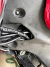
- Hide/zip-tie the wires behind the light assembly. You can stuff the flasher box and the two connectors for the main harness into the frame. To get the flasher box inside the frame simply remove the box, insert the connector and reattach. The flasher box sits well ahead of the battery, giving you easy access for any future replacement.
- Attach the mirror mounts to the handlebars. They go between the grips and the controls. The clutch side fits nicely…not so nice on the throttle side.
Honestly, the home-brewed solution I have on my blue FZ was significantly easier to install (and I had to design it on the fly), took a fraction of the time, and looks unique. I wouldn’t use one of these kits again. It was a very unsatisfying job but it does have the OEM FZ6N look.
Attachments
Last edited: