• Welcome to the Yamaha FZ6 Forums. Member registration disables ads and allows you to post and share. Register Here.

FZ6 S2 – Dash/cluster dies randomly,

Sandseller

New Member
Joined
Jun 19, 2026
Messages
10
Reaction score
13
Points
3
Location
Germany
Visit site
Hi all,

I've been fighting an intermittent instrument cluster failure on my FZ6 S2 (RJ14, 2008, ~30,000 km) since last season and I've hit the limit of what I can diagnose myself. Hoping someone here has seen this before or knows the weak point. I am getting frustrated with this bike, having constant problems

Symptom:
- Cluster (LCD + tacho) dies randomly, mostly while riding, no fixed pattern
- No stumble/hesitation from the engine when it happens. The ECU/fuelling keep running fine
- Turn signals and neutral light keep working independently
- Sometimes it comes back after an ignition off/on cycle, sometimes only after pulling the backup fuse + waiting a bit or pulling the sub-harness and waiting before connecting again, sometimes only after a long period sitting, and once it stayed dead for the rest of a ride
- Doesn't matter if the ignition is just on or if I ride
- Last season I swapped the fuses and it worked after that so I thought it would be that, This year I had no problems until this morning (it rained yesterday, the bike sits outside)

Already checked/ruled out:
- Replaced battery (AGM), replaced air filter, cleaned fuse holder contacts - no lasting effect
- ECU ruled out (engine runs perfectly fine during the failure)
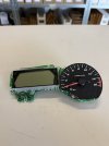
- Removed the cluster, bare PCB (out of its housing) ran fault-free for an extended period (5-10min), the fault only came back after full reassembly (housing + fairing)
- Wiggling the left front sub-harness connector partially reproduced the failure, but not reliably or at one fixed spot
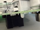
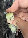
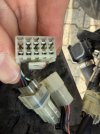
- Visual inspection of the board: no bulged capacitors, no visible corrosion, solder joints on the main connector (CN1) look clean (see photos)
- checked voltages last year, seemed low so I swapped the battery this year

What I planned to do:
- check voltages again
- try to clean every connector I can get my hands on

(Other problems that may or may not be relevant:
- I am unsure if my bike runs shitty or if the FZ6 is just like that. It's hopping at low rpm, sounding like a turd too. I actually wanted to change all spark ignitors and run Techron through a full tank before the cluster problem came back)

Questions for you:
1. Has anyone seen this exact failure on an FZ6/Fazer 600 S2 cluster?
2. Any known weak points on this cluster (specific components, solder joints, connectors)?
3. Has anyone repaired this themselves, what turned out to be the cause?

Thanks for taking a look!

Photos:
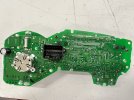
IMG_8337.JPG
IMG_1295.JPG
 
Another member had a similar problem with the readout. Have heard back as to whether they looked into and of the testing suggested.
Is you clock time remaining the same after the failure?
 
Yes I read several threads about this problem but they all seem to have different solutions to the problems. I will check the white w/ red tracer wire next time I am working on the bike. At this point I kind of hope that the failure persists so I can diagnose and get rid of it
The clock does not reset unless I disconnect the cluster manually.
 
I agree with Motogiro, if you were losing the main ground, the clock would reset.

I would get a multimeter and take a closer look at the continuity from the ECU to the connector at the front left of the bike and then the wires from the connector to the instruments.

Also look at the pins on the connectors for corrosion and check the wires that go into them for intermittent contact.
 
If you can look at how the LCD readout is attached to the circuit board. A popular way I've seem then attached is with little conductive rubber nibs or strips.
I would look closely with a magnifier at the circuit lands near the wires that enter the board. Probably wouldn't hurt to hit each solder joint where the plug is attached on the board. wouldn't hurt to use an isolated soldering iron.
 
Thank you two for the suggestions. I did check the connectors for corrosion and dirt but they do look clean. However, I will try cleaning them, using WD40 contact cleaner and dielectric grease next. Tinkering on the pcb will be my last resort, to get to the connector you have to desolder the lcd first.

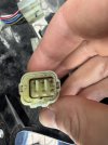
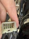
IMG_1297.JPG IMG_1290.JPG IMG_1288.JPG IMG_1292.JPG IMG_1286.JPG
 
What Motogiro mentions about the LCD connects to the circuit board reminds me of when I had a problem with the LCD flickering or fading, because it's an Induction Coupling, ie just two bits of conductive rubber pressed together.

The only reason I didn't mention it is because you said the tacho failed as well, but, from what I understand, on the S2, it's a different connection unlike the LCD rev counter on the S1.

This thread might be of interest, none the less: https://foc-u.co.uk/mybb/showthread.php?tid=80897
 
So today I drove the bike to work as I have more space and tools there. The cluster worked perfectly this time, no flicker at all. My main suspect is water damage/moisture now because the last time it flickered it rained the day before and since then it was warm and dry.
Time to spray water around the bike to find the culprit I guess?
 
Agree that it is probably moisture related. Are you in a fairly humid location?
The issue is likely inside the LCD assembly, related to the elastomer or conductive strips others have mentioned.
When you have it opened up with the board out (like in your photo), if you can put that into a low heat drying setup it might solve it. Otherwise the LCD should probably be dis-assembled and the elastomers and their contacts cleaned/de-oxidized. Isopropyl on the strips and a pencil eraser to the contacts is a method often used. If you don't feel comfortable doing it, an electronics specialist that works on LCD type displays should be able to do it for you.
 
It can get rainy here, but it’s been bone-dry in Germany for about 10 weeks. Sunday was the first heavy rain in quite a while.

Today I was able to remove the fairing and systematically hosed down various parts of the motorcycle: the fuse box, all the connectors in the back, front, and under the tank, and the instrument cluster housing. Unfortunately, despite using several liters of water, I couldn’t reproduce the fault. I took the opportunity to jiggle, pull, and check every connector again. I tugged on cables and ran through every possible nightmare scenario for the wiring harness. I couldn’t trigger a failure at all.

I’m not entirely sure what’s meant by “conductive strips.” The LCD in the S2 version is soldered to the circuit board, if that’s what’s meant.

Since the failure has so far always occurred in connection with cooler and rainy weather (around 15 degrees C, with rain in the days leading up to it), I’m currently assuming it’s a combination of both factors, not just the rain alone. I just don’t know yet whether it’s the cables or the PCB itself that’s affected.

For now, I’m sticking to my plan to treat all connectors with contact spray—red/green, red/white, yellow/blue—and to check the ground cables and treat them with dielectric grease if necessary.

After that, I’d probably take a closer look at the PCB. However, since it doesn’t appear to be corroded, a component failure would be the most likely cause here.

Edit: http://www.fazerclub.ru/manuals/FZ6/Yamaha_FZ6_2007_ALL_VERSIONS_Service_Manual.pdf last page would be the schematic to my bike
 
I’m not entirely sure what’s meant by “conductive strips.” The LCD in the S2 version is soldered to the circuit board, if that’s what’s meant.
When you desolder the LCD, you should find that the LCD assy. has it's own little circuit board that those pins connect to. Think of all the segments and different things that are displayed, there are not enough pins there for that.
That mini board would connect to the glass display by way of these conductive strips, sometimes also called zebra strips or elastomeric strips. There's lots of videos showing how to service them; whether for a multi-meter or a laptop, the principle is the same.
 
Quick update: I was able to tinker with the bike a bit more on Friday. However, due to the long periods with the ignition on but the bike not running, the battery got too low while I was measuring the voltages. I was still able to measure 10.3V at R/W and R/G (10V on the data line, by the way), but when I tried to start the bike to check the voltages at idle, the starter relay just kept clicking. I then checked for continuity, didn’t find anything unusual, and treated all the connectors with contact spray and cleaned them up a bit. The battery needs to charge now, and then I’ll be able to measure the voltages at idle.

I didn’t find anything unusual again, except for a ground connection near the instrument cluster on the frame, which was a bit rusty. I cleaned that up. The color is black and it's not the same ground as the black/white cable from the cluster connection.

I also found a shop in Germany that tests and repairs instrument clusters. The test costs only 40 bucks, so I’m sending the cluster in. If they find a fault, I’ll be on the safe side. If they don’t find anything, I’ll know it’s a wiring issue.
 
I received a response from the shop today stating that the processor controller or the main processor is defective. Even when I asked for more details, they didn’t tell me exactly what that meant.
However, since the store has a good reputation, I agreed to the (very expensive) repair, as I don’t have many other options.
I’ll take a look at the circuit board as soon as the cluster is back. Hopefully, that will be the root of the problem.
 
I got the cluster back today.
Much to my dismay, the shop had sealed the cluster, which I consider a big no-no. Since I still wanted to replace the gasket (and see what had been repaired), I opened the enclosure anyway.

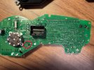
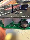
As far as I can tell, a component in the circled area was replaced. You can’t really see it because of the tachometer, but it’s safe to assume it was the immobilizer LED. All other (visible) solder joints look unchanged; he couldn’t have replaced anything under the display. Since I’m not quite sure how to remove the tachometer, I can’t check if anything on the surface underneath was replaced.

It’s raining right now and I’m waiting for new spark plugs, so it’ll be a few more days before I can drive again.

If I don’t check in again, it was either my re-cleaning of the connectors or this component. For almost €300 and given my experience with an unfriendly repair shop, I’m hoping for the latter.
IMG_1434.JPGIMG_1433.JPGIMG_1431.JPG
 
Is the bottom of the LCD anchored to the board? If not, they may be able to bend it up and replace processor if it is underneath (without desolder or removal of LCD).
 
I think the LCD is soldered directly to the PCB and bending it up may be possible but seems risky. No idea what the shop did, I couldn't find anything besides these solder spots. I am trying to help people because this fault will become more prominent as machines get older. If you can solder and know where to look it is an easy and cheap job but if you don't know where to start people might selling their bikes off or even worse and put it in a junkyard.
 
Desoldering and doing anything to the traces (like desolder and remove LCD from circuit board) is also risky. With modern flimsy traces and boards, it is often less risky to bend the long pins rather than removal.
That is why I suspect they may have done it that way. But is only possible if there are pins only along one side of the LCD.
Was there no expensive part listed on the invoice?
 
Back
Top