How to's: Fuel Pump Repairs, Charging System & Battery Diagnoses, Brake Bleeding & Inspection, Error Codes, Vibration Induced by Ignition System. See index!
***
FUEL TANK, FUEL PUMP, AND FUEL GAUGE, REPAIRS AND TESTING!
***
CHARGING SYSTEM AND BATTERIES
***
LEAKAGE CURRENT KILLING YOUR BATTERY??
***
Vibration! A cure for bad vibrations, Spark Plug Caps!!
***
2007++ FZ6 Parts Reference Diagram/Images X46 (Parts fiche)
***
METER DIAGNOSTIC MODE & ERROR CODES
***
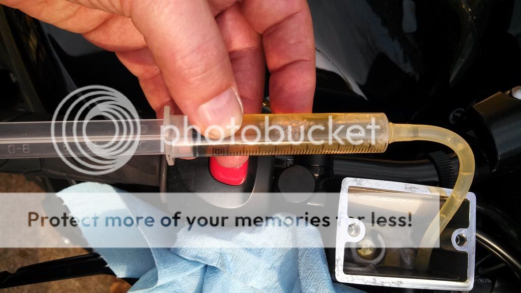
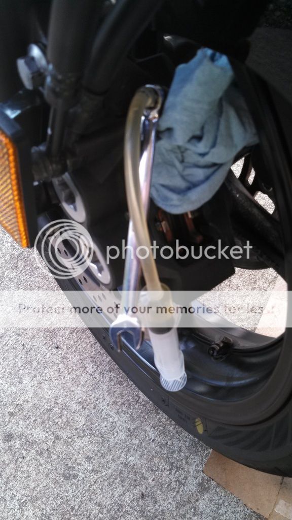
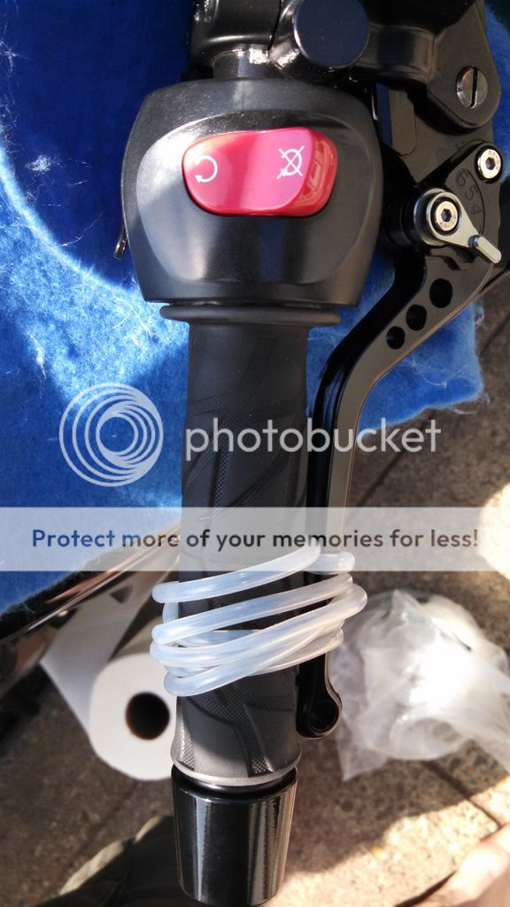
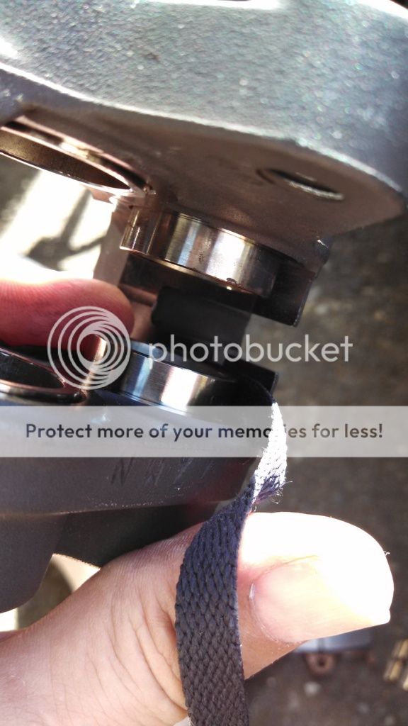
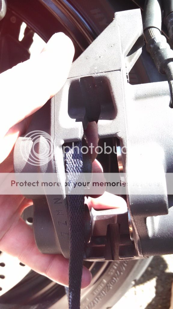
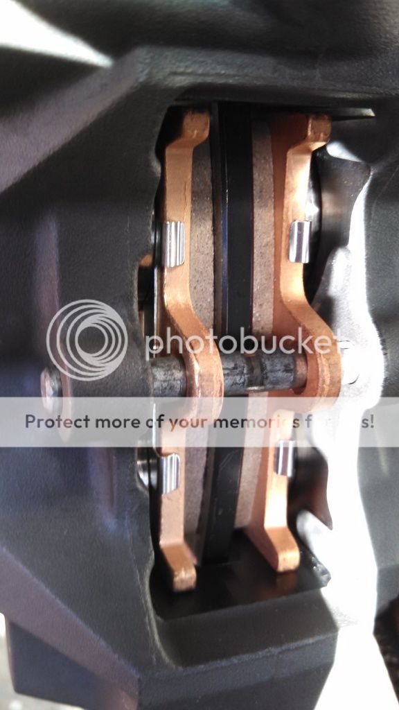
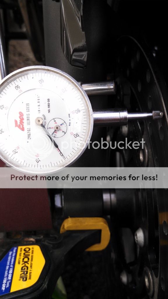
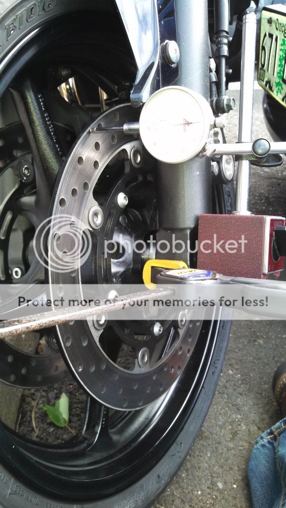
BRAKE BLEEDING, CALIPER AND PAD INSPECTION
***
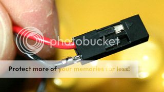
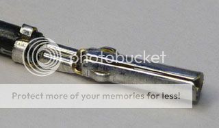
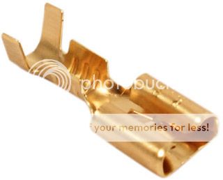
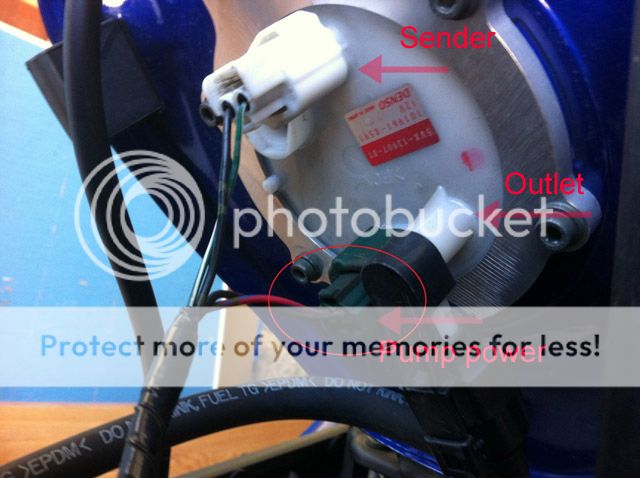
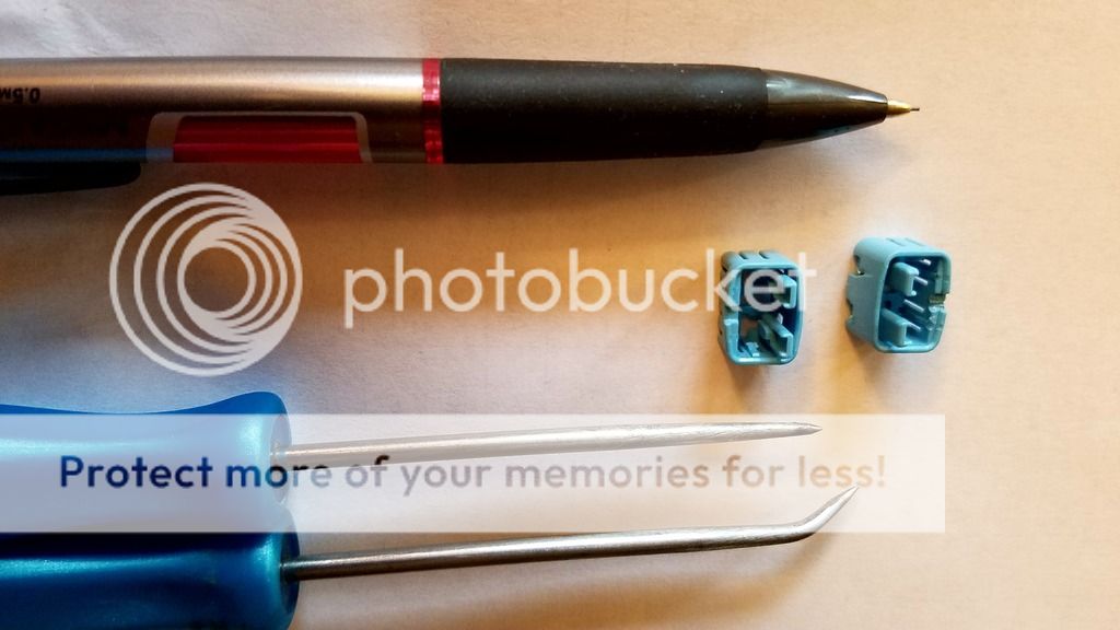
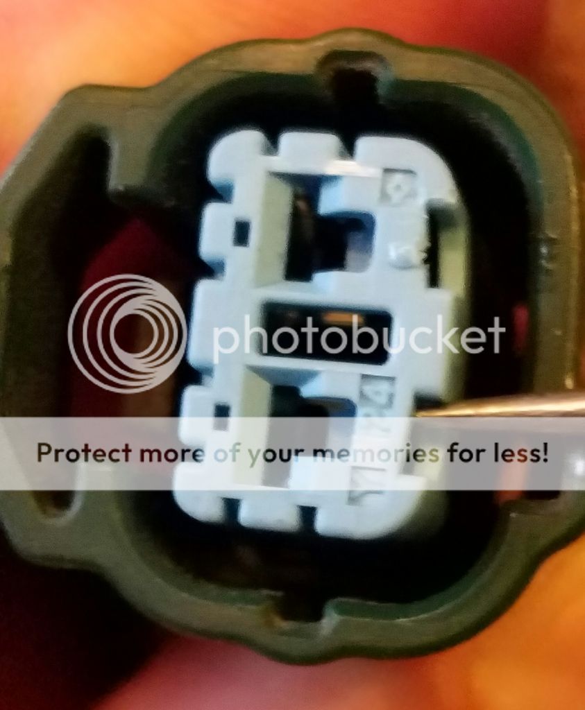
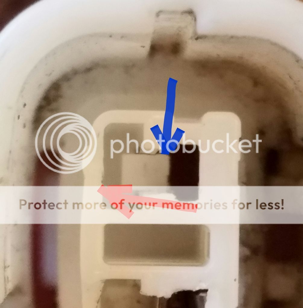
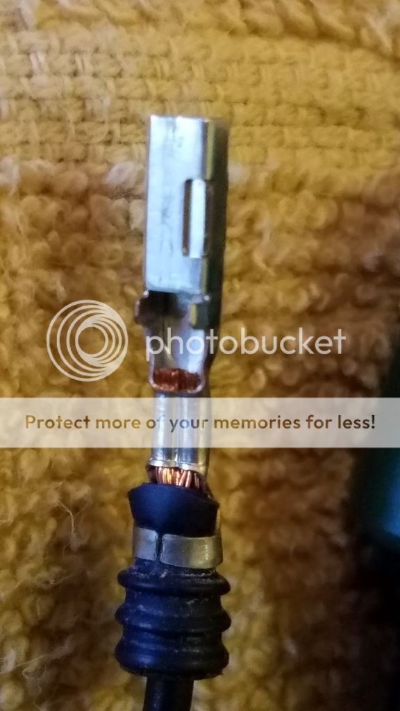
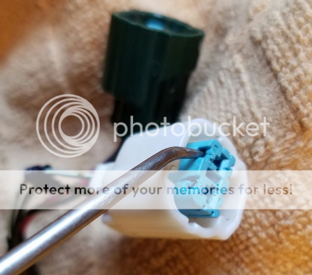
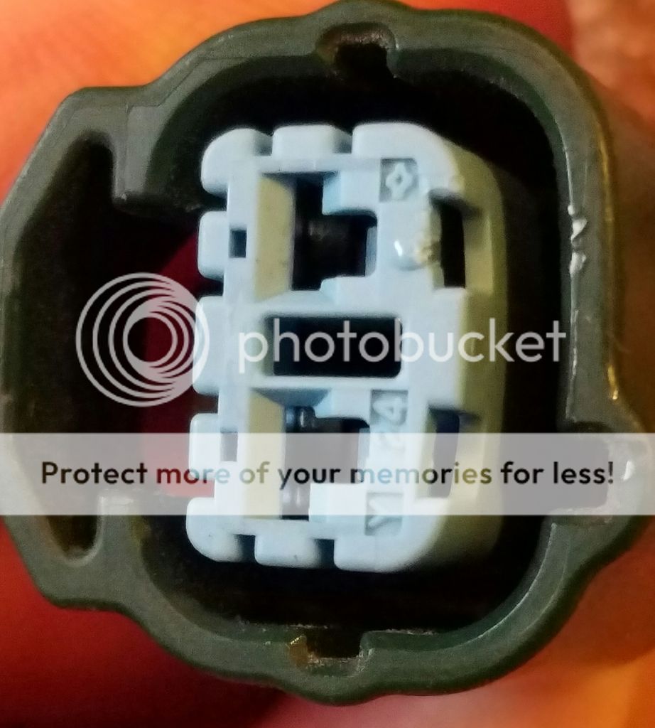
Fuel Pump Power and Sender Pin Extraction 2017-01
**************************
Waiting for a how too...
***
THE KILL SWITCH
**************************
CHAIN SLACK
**************************[/B]
**************************
Did information from 600riders help you resolve a problem?
If so, please consider a donation to the site:
Link --> Click to donate! Thanks!
XXXXXXXXXXXXXXXXXXXXXXXXXXXXXXXXXXX
EDIT LIST:
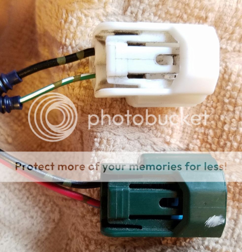
2017-04 added fuel pump connector
2014-10-31 Made proper hyperlnks
2014-08-12 Added Brake Bleeding, pad inspection etc.
2014-07-21 Added Diagnostic codes, tests, process to view it.
2014-05-18 Added leakage current, post 10, spark plug caps, and parts diagram
2014-05-08 Add donation link
2014-04-12 modify index
XXXXXXXXXXXXXXXXXXXXXXXXXXXXXXXXXXX
If you find something to be in error post up (or PM) and we'll correct it! Tks and Ride Safe!
***
FUEL TANK, FUEL PUMP, AND FUEL GAUGE, REPAIRS AND TESTING!
***
CHARGING SYSTEM AND BATTERIES
***
LEAKAGE CURRENT KILLING YOUR BATTERY??
***
Vibration! A cure for bad vibrations, Spark Plug Caps!!
***
2007++ FZ6 Parts Reference Diagram/Images X46 (Parts fiche)
***
METER DIAGNOSTIC MODE & ERROR CODES
***
BRAKE BLEEDING, CALIPER AND PAD INSPECTION
***
Fuel Pump Power and Sender Pin Extraction 2017-01
**************************
Waiting for a how too...
***
THE KILL SWITCH
**************************
CHAIN SLACK
**************************[/B]
**************************
Did information from 600riders help you resolve a problem?
If so, please consider a donation to the site:
Link --> Click to donate! Thanks!
XXXXXXXXXXXXXXXXXXXXXXXXXXXXXXXXXXX
EDIT LIST:
2017-04 added fuel pump connector
2014-10-31 Made proper hyperlnks
2014-08-12 Added Brake Bleeding, pad inspection etc.
2014-07-21 Added Diagnostic codes, tests, process to view it.
2014-05-18 Added leakage current, post 10, spark plug caps, and parts diagram
2014-05-08 Add donation link
2014-04-12 modify index
XXXXXXXXXXXXXXXXXXXXXXXXXXXXXXXXXXX
If you find something to be in error post up (or PM) and we'll correct it! Tks and Ride Safe!
Last edited: