- Joined
- Aug 24, 2007
- Messages
- 889
- Reaction score
- 79
- Points
- 28
- Location
- Alberta, Canada (GMT-7)
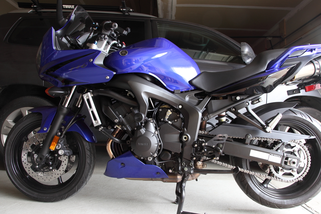
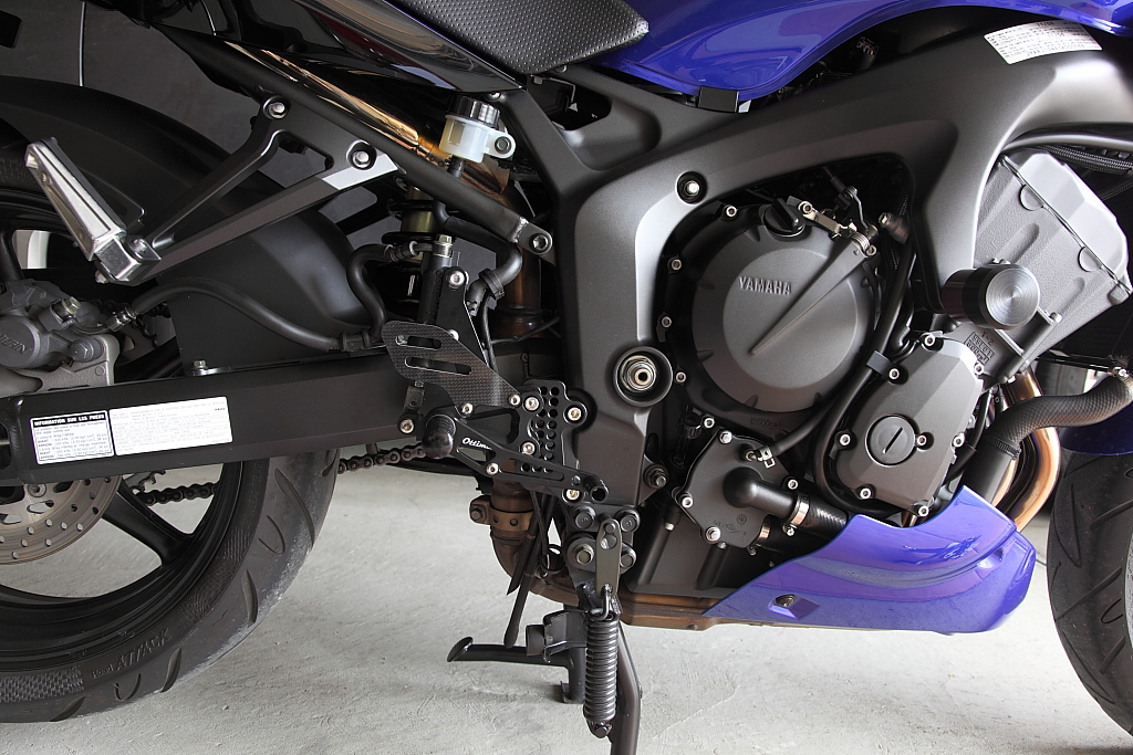
During this installation I took a few pictures in hopes of providing some useful documentation in what my opinion is on installing the Ottimoto rear sets on my 2007 FZ6. BTW, you can click over the pictures to access a higher resolution picture. Prior to and after the installation of the shifter and brake side sets, I took some measurements to compare the stock setup to the resulting Ottimoto setup, captured in another thread of mine…
 www.600riders.com
To begin, I dealt with and bought my rear sets from Ron Fung at Ottimoto. Ron handled the order and the shipment arrived in a timely manner from Hong Kong. The pieces were well packed and organized.
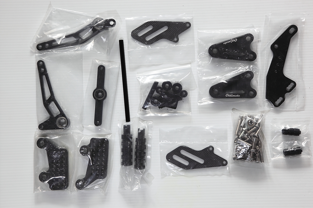
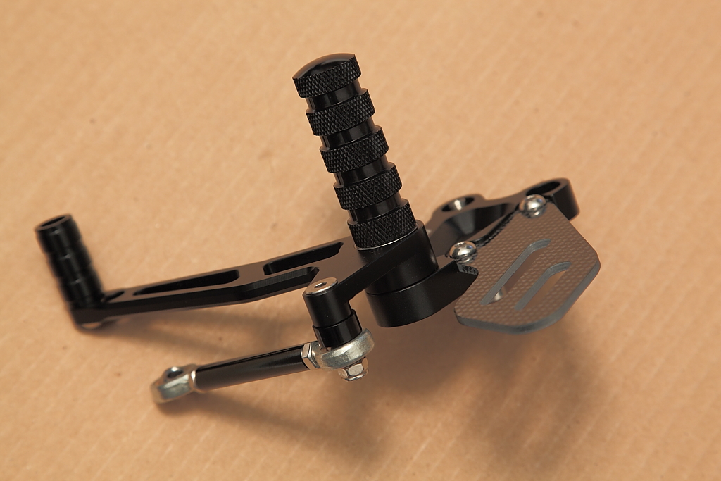
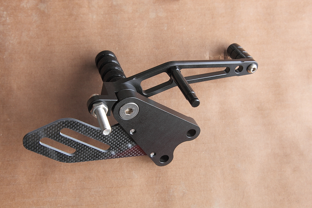
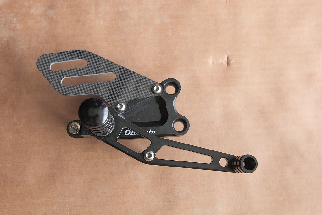
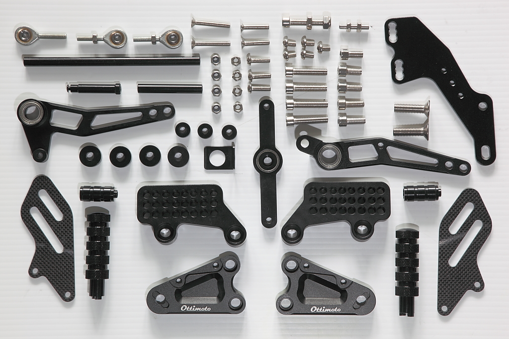
I took a picture of all the pieces laid out straight from the package to inventory all the parts in case the dog decided to run off with a piece.
I decided to start with the shifter side as it looked less complicated and easy enough to do in a short duration of time and gain that needed accomplishment feeling to plow along.
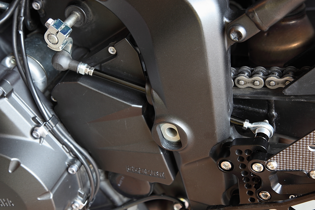
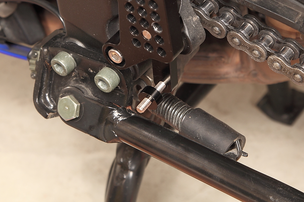
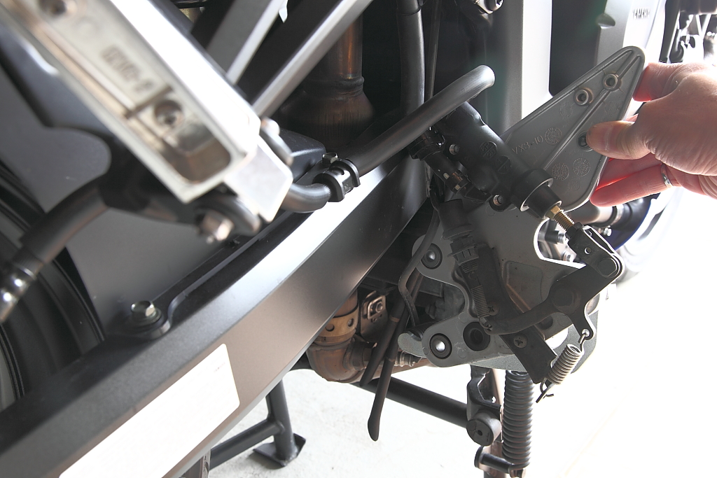
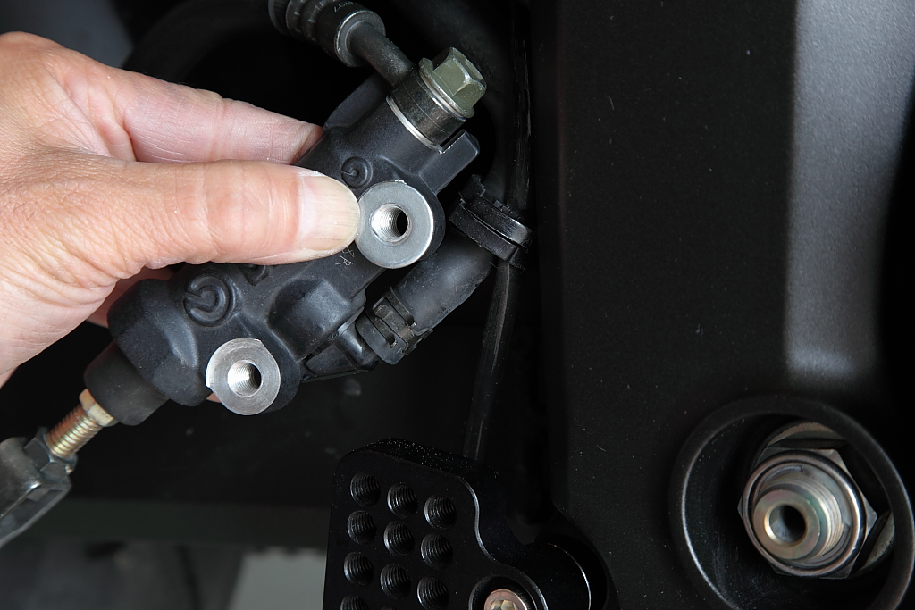
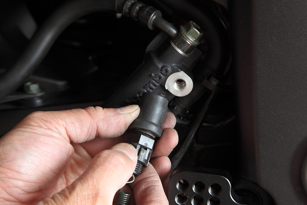
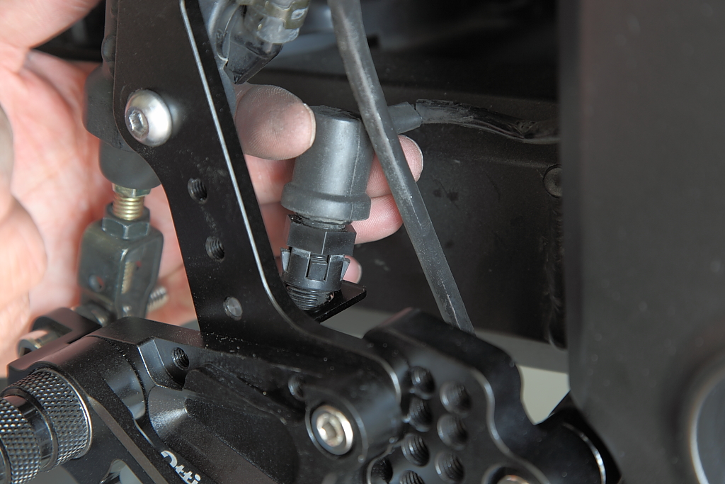
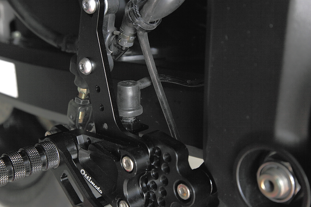
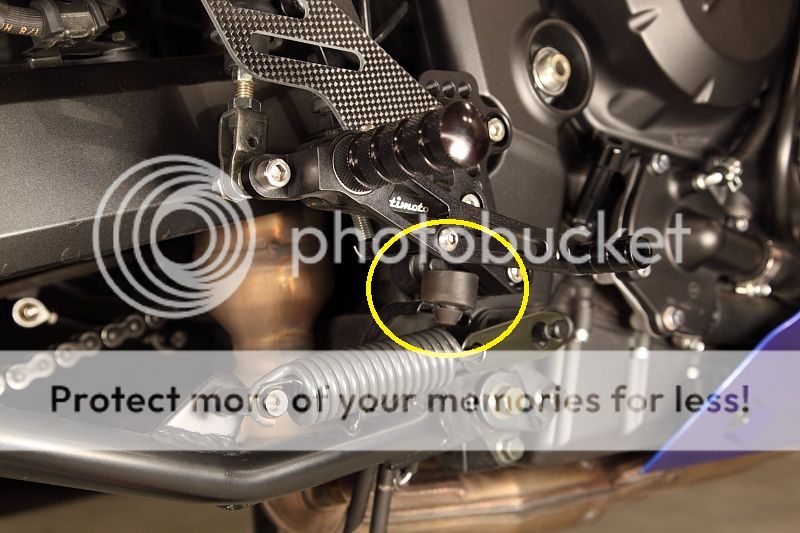
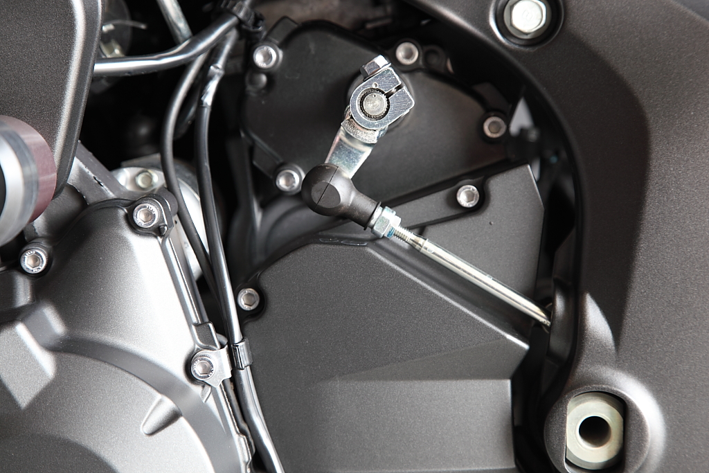
First thing is to pull the rubber boot back exposing the rod end of the shift rod at the shift arm and remove the bolt and spacer behind the rod end.
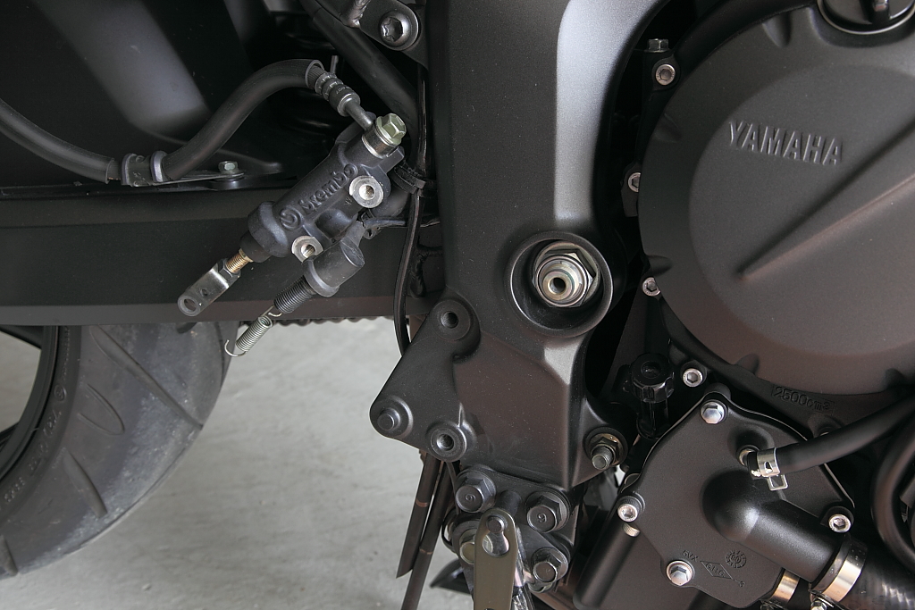
Remove the two bolts holding the rear set to the frame and wiggle rear set to free the rubber grommet in behind to the frame, then moving the rear set rearward sliding the shift rod through the frame to free the whole assembly. Sorry, no pictures here since I thought this was obvious.
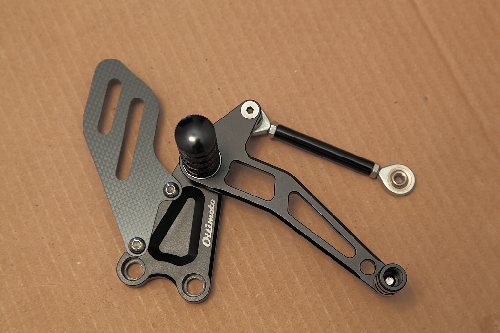
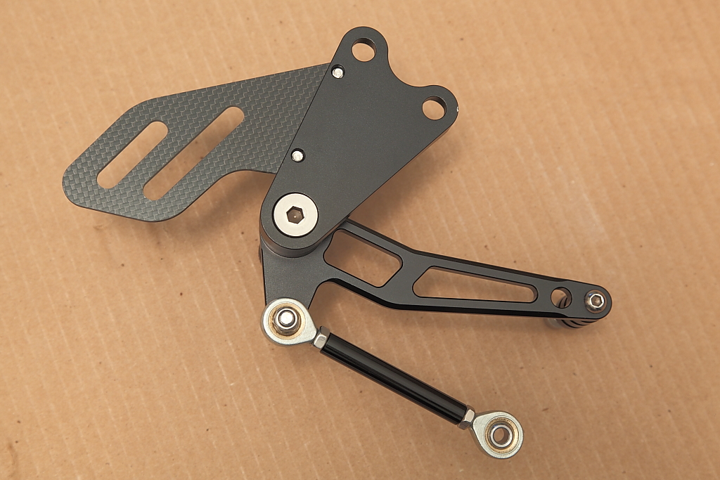
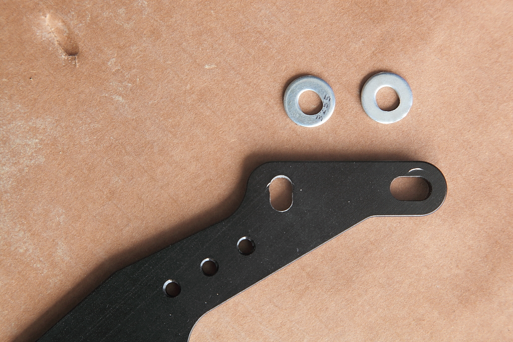
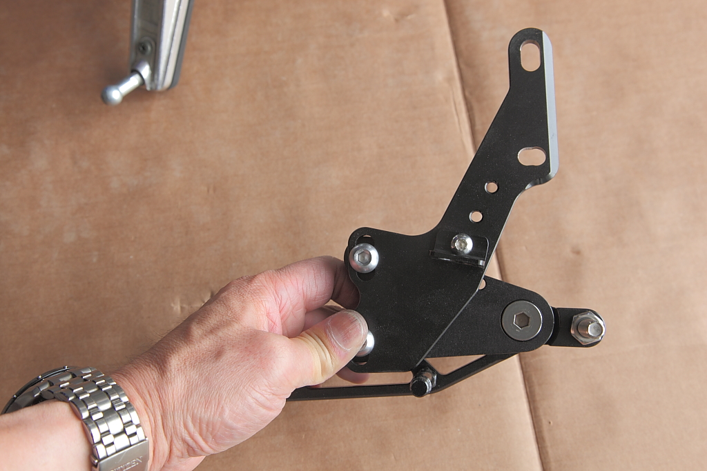
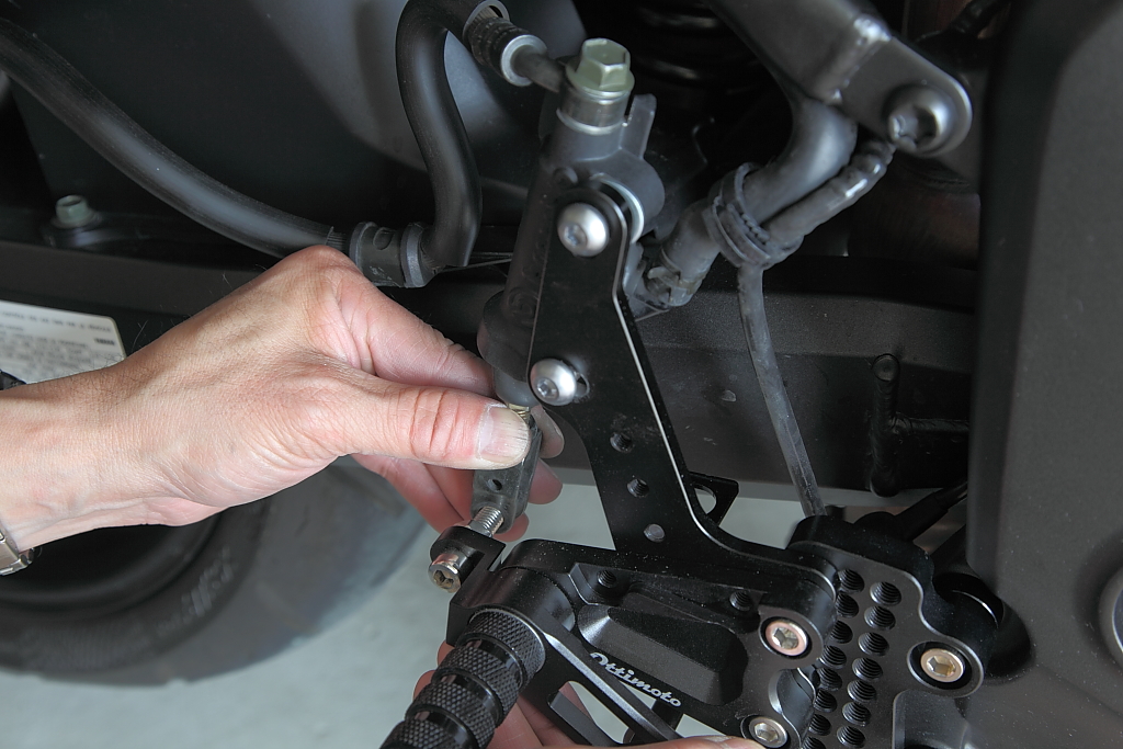
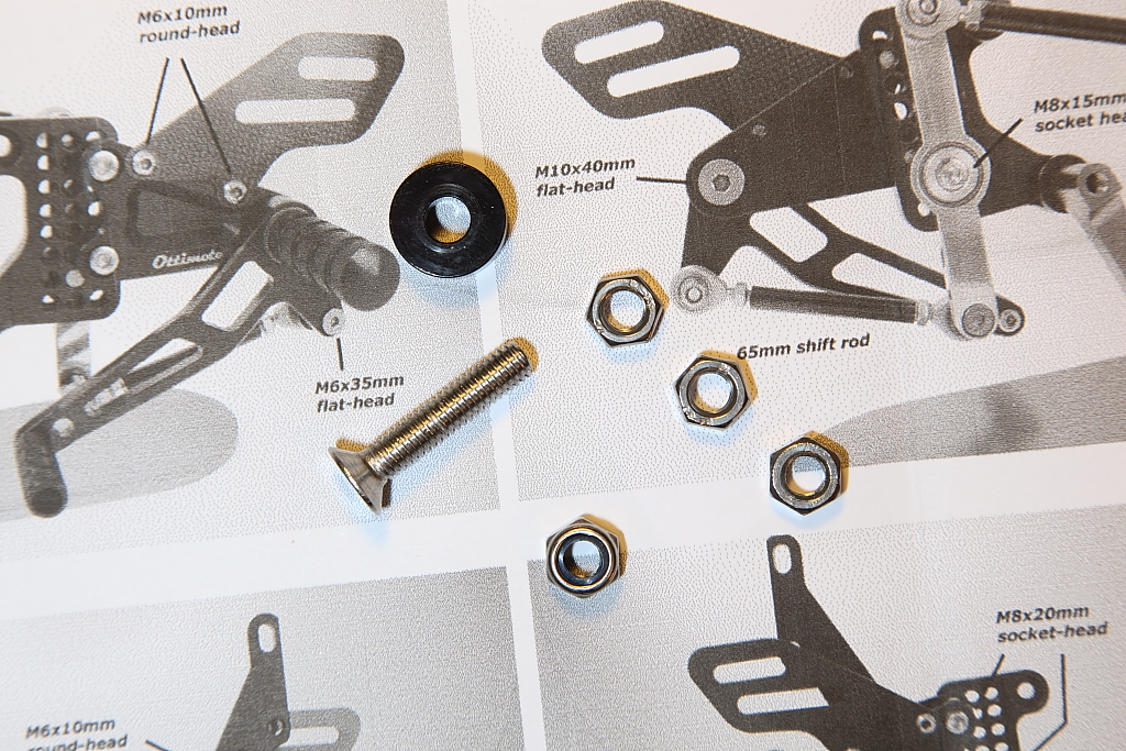
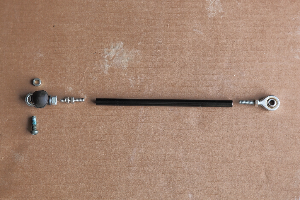
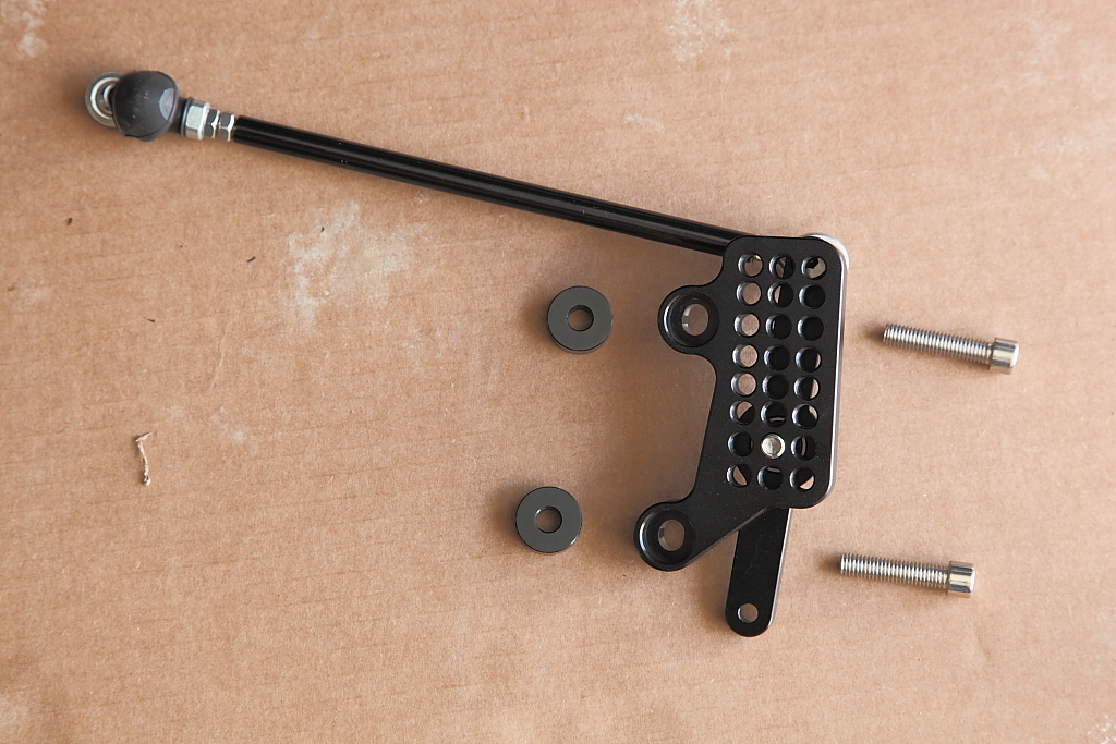
Remove the rod end from the shift rod that was at the shift arm as it will be used on the new shift rod. The new shift rod has the stock rod end on the left with a right hand thread, and the right side rod end is a left handed thread. This picture shows the pieces that make up the new shift rod.
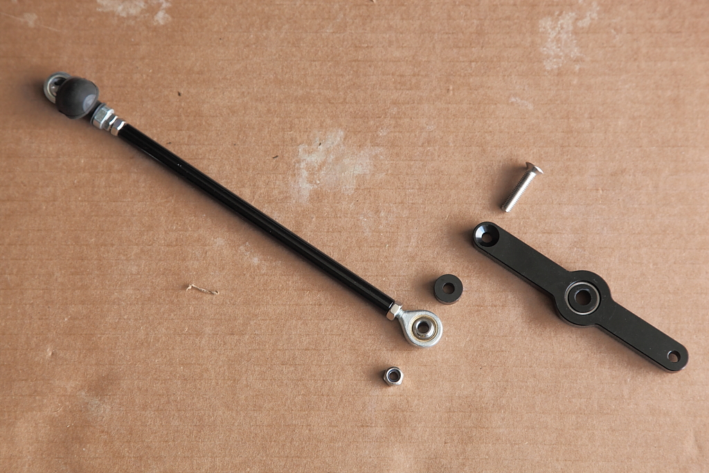
Next attach the shift rod to the link arm using a M6 flat head screw, spacer between the link arm and the rod end, and a nylon lock nut.
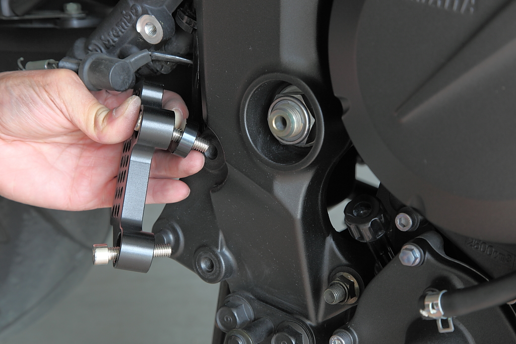
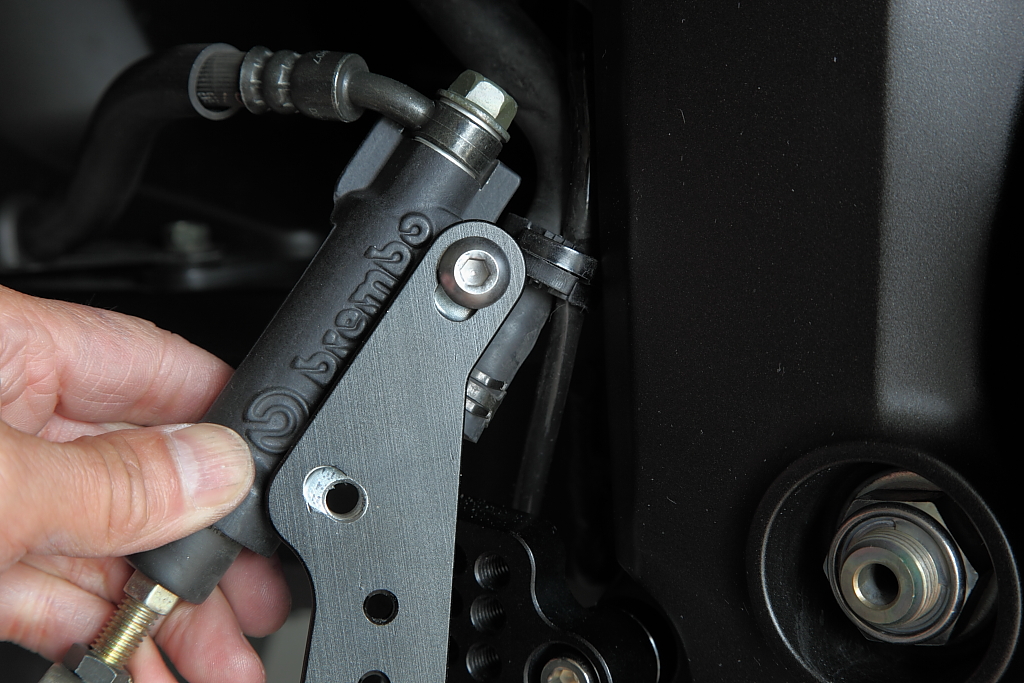
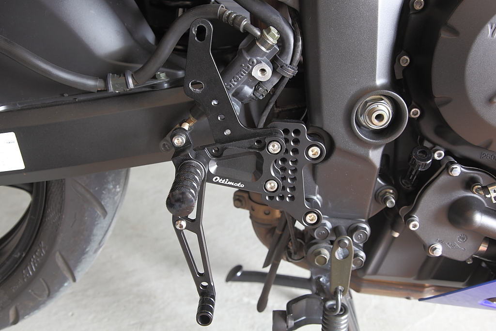
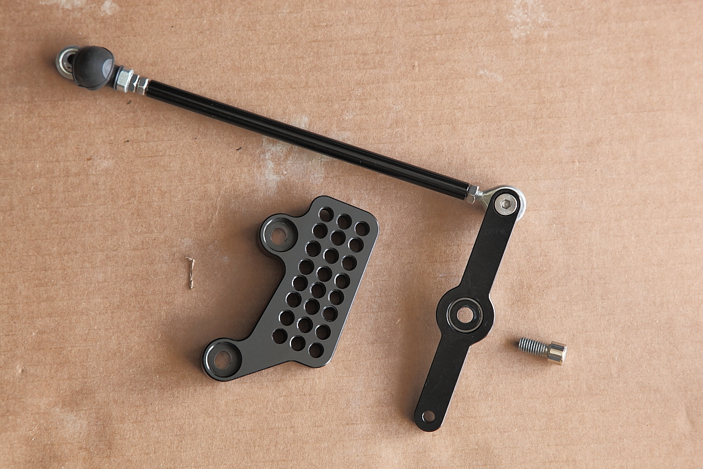
Using a M8 cap screw, attach the shift rod/link arm assembly to the setback plate in the middle set second from the bottom hole.
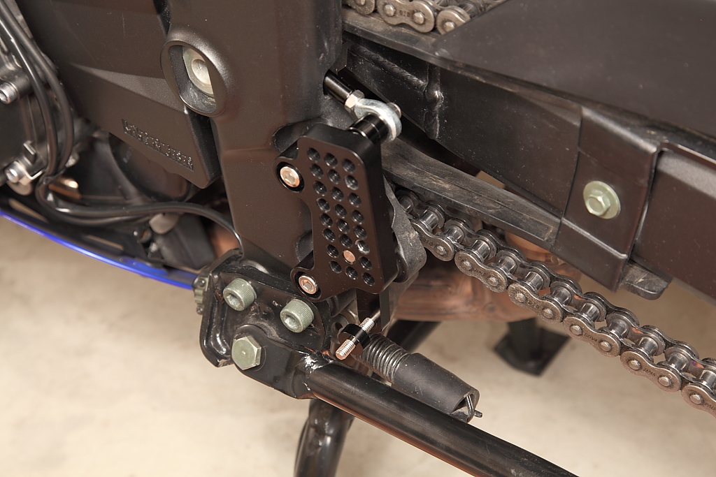
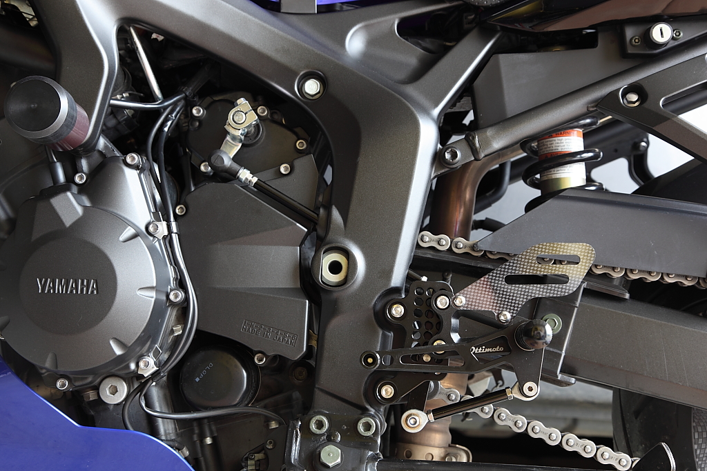
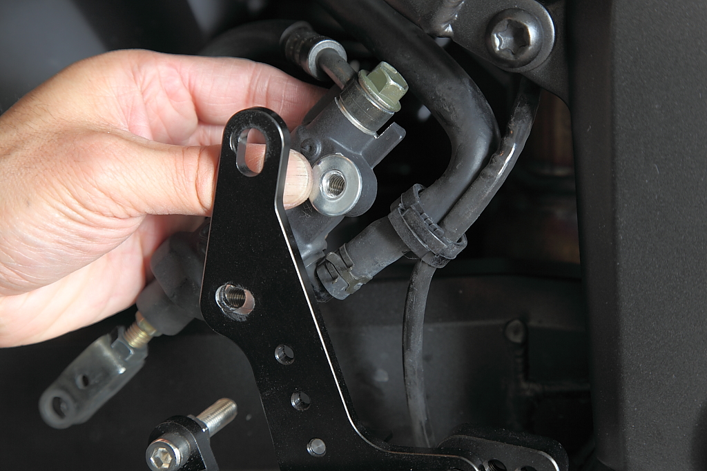
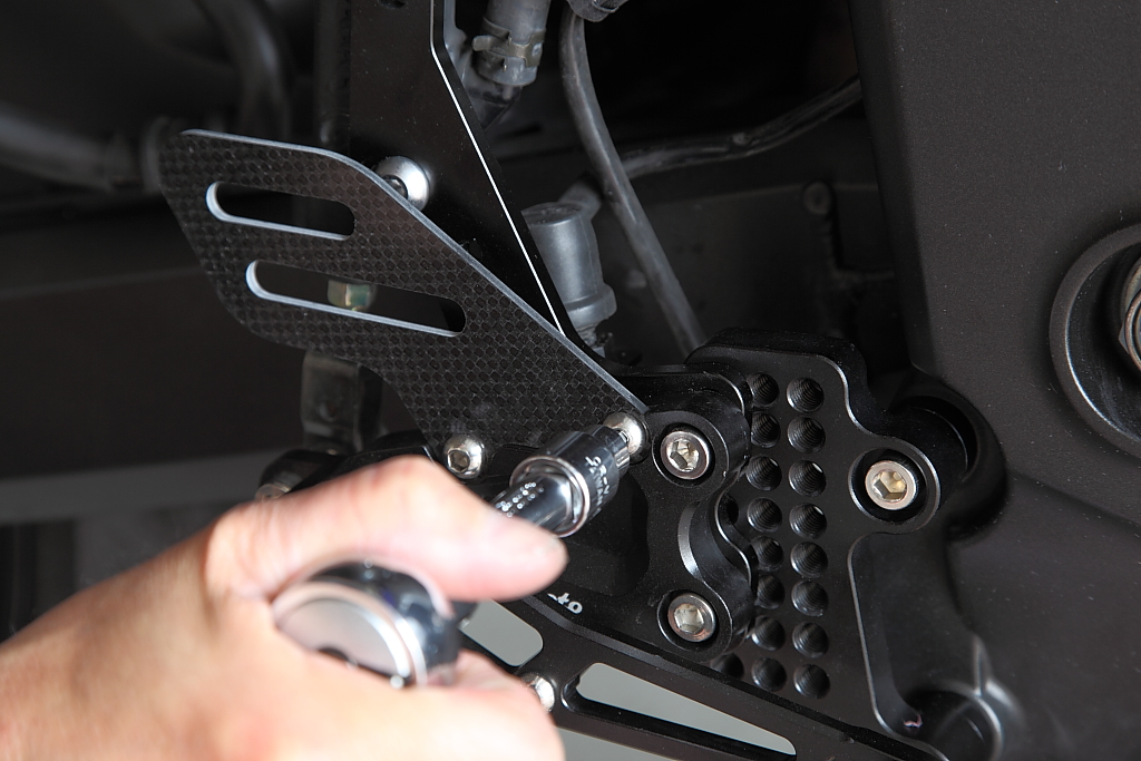
This assembly will now be attached to the frame using two of the M8 cap screws and two of the spacers.
Feed the shift rod through the frame, insert the cap screws through the setback plates, and add a spacer behind it.
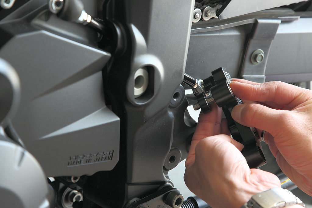
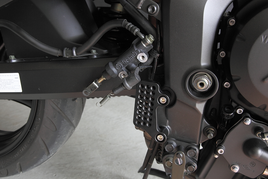
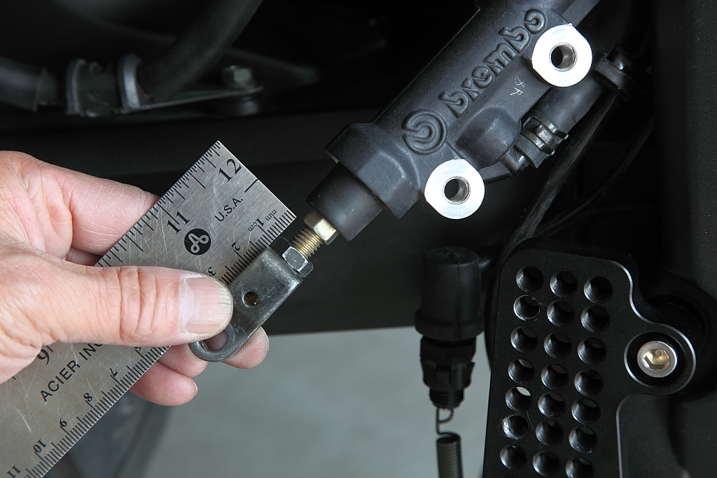
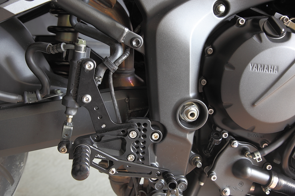
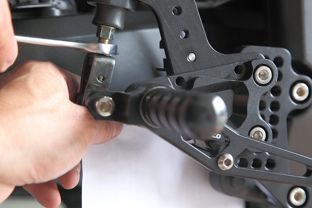
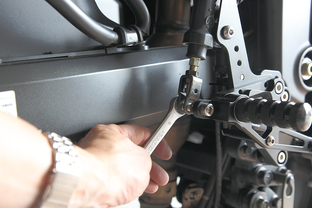
The torque spec on the stock bolts were 22 ft•lbs so I torqued these to the same spec. Re-attach the rod end to the shift arm with the stock screw and spacer.
Ottimoto Rear Set Comparison
Rainy days are for staying in the garage and putting on some Ottimoto rear sets. As I was installing them, I took some measurements to compare the original setup to the end result. Starting with the shifter side, a line is connected from the front axle to the rear which will be the reference...
To begin, I dealt with and bought my rear sets from Ron Fung at Ottimoto. Ron handled the order and the shipment arrived in a timely manner from Hong Kong. The pieces were well packed and organized.
I took a picture of all the pieces laid out straight from the package to inventory all the parts in case the dog decided to run off with a piece.
I decided to start with the shifter side as it looked less complicated and easy enough to do in a short duration of time and gain that needed accomplishment feeling to plow along.
First thing is to pull the rubber boot back exposing the rod end of the shift rod at the shift arm and remove the bolt and spacer behind the rod end.
Remove the two bolts holding the rear set to the frame and wiggle rear set to free the rubber grommet in behind to the frame, then moving the rear set rearward sliding the shift rod through the frame to free the whole assembly. Sorry, no pictures here since I thought this was obvious.
Remove the rod end from the shift rod that was at the shift arm as it will be used on the new shift rod. The new shift rod has the stock rod end on the left with a right hand thread, and the right side rod end is a left handed thread. This picture shows the pieces that make up the new shift rod.
Next attach the shift rod to the link arm using a M6 flat head screw, spacer between the link arm and the rod end, and a nylon lock nut.
Using a M8 cap screw, attach the shift rod/link arm assembly to the setback plate in the middle set second from the bottom hole.
This assembly will now be attached to the frame using two of the M8 cap screws and two of the spacers.
Feed the shift rod through the frame, insert the cap screws through the setback plates, and add a spacer behind it.
The torque spec on the stock bolts were 22 ft•lbs so I torqued these to the same spec. Re-attach the rod end to the shift arm with the stock screw and spacer.
Last edited: