- Joined
- Aug 24, 2007
- Messages
- 889
- Reaction score
- 79
- Points
- 28
- Location
- Alberta, Canada (GMT-7)
https://www.600riders.com/media/dp_071103_12-jpg.5413/I made a low beam wire harness in the Part 1 post related to this topic.
 www.600riders.com
Now I’m going to install it in the bike. Up to this point I haven’t been in the garage near the bike to do the dual light mod.
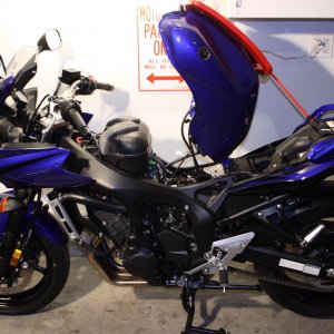
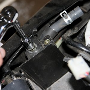
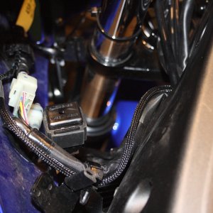
To get to the connector, it’s under the tank. Remove the seat and secure the tank. I used a bungee cord. Ensure that the wire leads to the tank aren’t being stressed otherwise disconnect them.
 www.600riders.com
 www.600riders.com
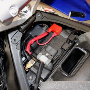
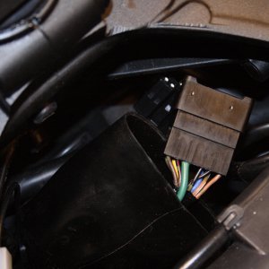
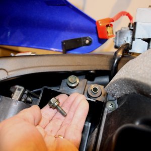
Remove the battery and the airbox. Remove the two 10mm bolts that hold the battery box in place and slide the box rearward. The connector is hidden in a rubber boot just inside the frame.
 www.600riders.com
 www.600riders.com
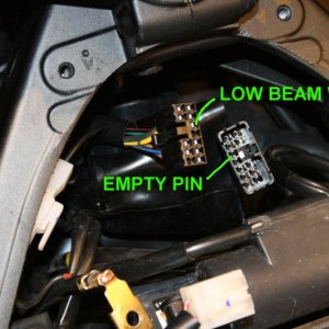
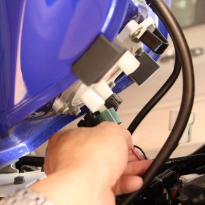
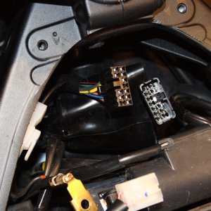
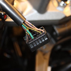
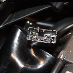
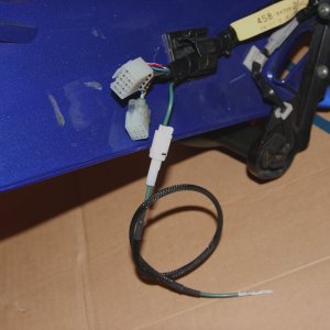
Unclip the connector halves apart. The bottom female connector in this picture goes to the left handlebar switch while the upper male connector runs off to various circuits on the frame as controlled by the switch.
 www.600riders.com
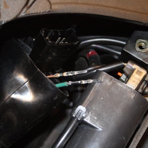
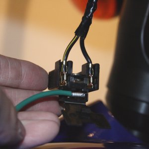
Feed the pin side of the wire harness, made in Part 1, through the frame, into the boot. This picture shows the fabricated pin to a factory stock one. It’s an exacting match.
 www.600riders.com
bd43's 07 Headlight Mod Part 1
In another post, I mentioned the left handlebar switch where the high/low beam switch resides. I also talked about the connector from the left handlebar switch mating to the wiring harness on the frame side that wanders off to the lights, horn, etc...
Now I’m going to install it in the bike. Up to this point I haven’t been in the garage near the bike to do the dual light mod.
To get to the connector, it’s under the tank. Remove the seat and secure the tank. I used a bungee cord. Ensure that the wire leads to the tank aren’t being stressed otherwise disconnect them.
dp_071103_12.JPG
dp_071103_13.JPG
Remove the battery and the airbox. Remove the two 10mm bolts that hold the battery box in place and slide the box rearward. The connector is hidden in a rubber boot just inside the frame.
dp_071103_14.JPG
dp_071103_17.JPG
Unclip the connector halves apart. The bottom female connector in this picture goes to the left handlebar switch while the upper male connector runs off to various circuits on the frame as controlled by the switch.
dp_071103_19.JPG
Feed the pin side of the wire harness, made in Part 1, through the frame, into the boot. This picture shows the fabricated pin to a factory stock one. It’s an exacting match.
dp_071103_21.JPG
Last edited:
 Get my bike on Friday.