2002 triumph sprint st valve check-

oldschoolsdime92

Junior Member
Joined
Jan 18, 2010
Messages
65
Reaction score
0
Points
0
Location
ohio
Visit site
I know this is a fizz forum, but the yamaha and the triumph have similar valve train setups, so I thought some of you maybe interested.

2002 Triumph Sprint st valve check; 19,803 on the clock.
I have spent the last roughly month calling around getting quotes on my valve check. I got price quotes that range from 150-375 (us) dollars. The small independent shops seemed to be cheaper than the triumph dealerships. I had one dealership in particular never even return my phone call. So with that being said, I decided I am halfway mechanically inclined, and could approach this task myself. With the help of a few on the forum, I have successfully checked my valves. It turned out to be a very straight forward job. I put together this little how to incase anyone else would be interested in giving it a shot.
The manual states the checking of the bike needs to be done cold, so your best bet would be to just start in the morning, before the riding bug bites you, and you HAVE to go for a ride. Keep your day free, as it does take some time. I started about 1230, and had it back together and on the road again by 730. This included Three trips to the parts store. The NGK spark plug book has the wrong number in their book, for the 02 sprint. Well anyways lets get this thing started.

100_0843.jpg


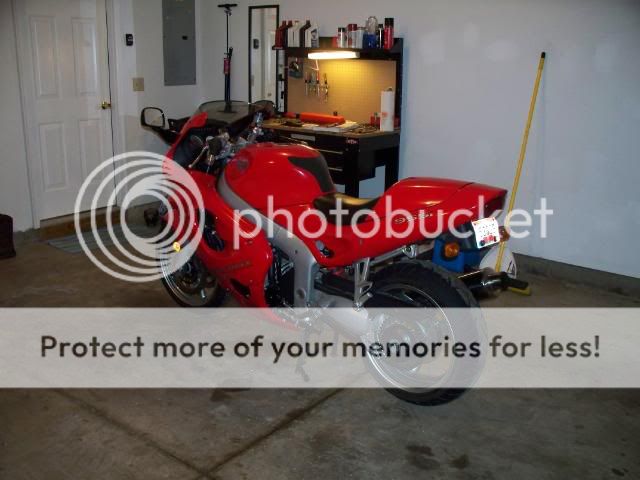
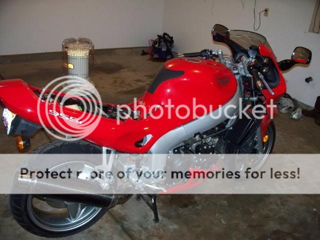
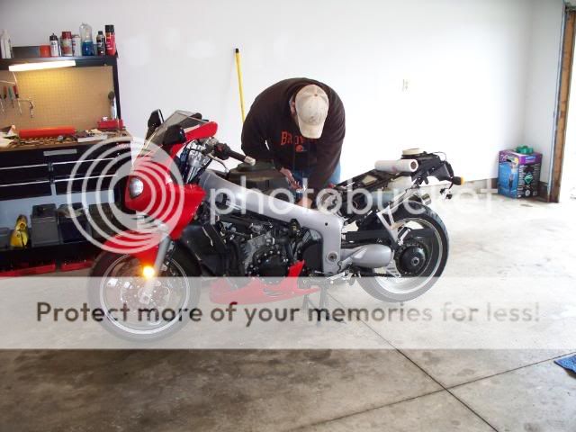
First thing you need to do, is get your bike up on the center stand, and to have a reasonable amount of room around the bike. Also, you may want to lay down a blanket to have a place to lay your fairings on.

100_0844.jpg


100_0845.jpg


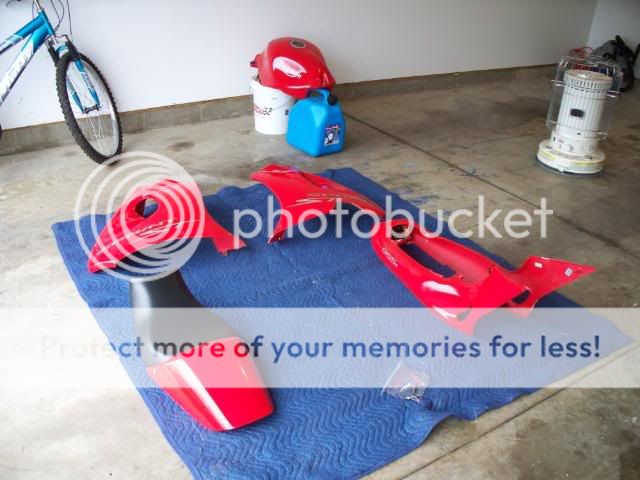
The manual states to remove the side fairings. On my bike particular, I could have checked the valves with the sides on. I’m not sure off the top of my head if it says the tail needs to go, but I removed mine just to give it a look over, as I have never dug into this bike. Here is my blanket of goods. We decided if someone were to come by and run off with my blanket, technically buying the parts new, would cost more than what I paid for the bike!

100_0846.jpg


100_0847.jpg


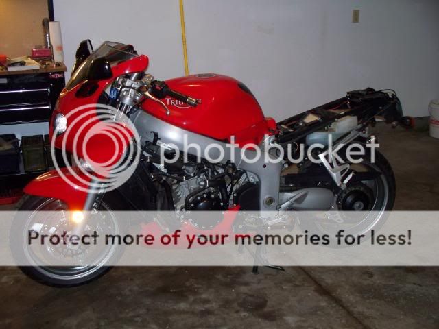
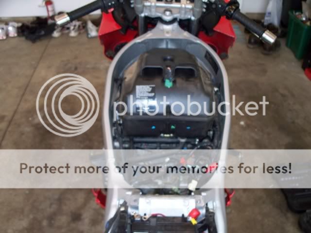
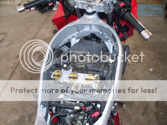
Now here she is with the tank off. This is where it gets interesting. There are two quick connect hoses, which It appears I do not have pictures of. They are very easy to unhook, but the manual says they will be self sealing once removed. One of my certainly was not self sealing, as you can see its sitting on a 5 gallon bucket, It spent the afternoon dribbling into that bucket. There was a vent tube, and an overflow tube, both that once unhooked will drop down onto the ground under the bike. There is an electrical plug on the fuel pump, and another plug under the tank. You can unhook everything you see on the side, and then lift the tank up and get the connector underneath. This is where its helpful to have a buddy or someone to help you out. I should have replaced mine with the metal fittings offered from team triumph, but I didn’t. The recall work on the original fittings had been already done.

100_0848.jpg


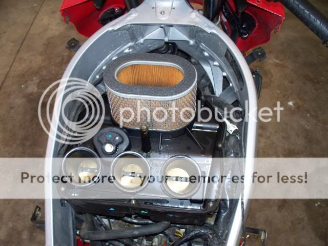
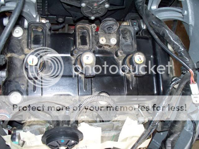
Heres the airbox. Right in the middle on top, you can see a sensor. Once I started removing hoses and wires, I thought it might be a good idea to label them with a piece of masking tape and a sharpie marker
 
Last edited:

oldschoolsdime92

Junior Member
Joined
Jan 18, 2010
Messages
65
Reaction score
0
Points
0
Location
ohio
Visit site
]
100_0855.jpg


There was a sensor on top of the air box, and then on the bottom of the air box, you have a sensor on the right side, and then a bigger hose in the middle, and a smaller hose on the left.
Once I removed the lid to the air box, I discovered I had the factory air filter. If your filter is dirty, this is a good opportunity to give it a change. Now I noticed something odd, once I was in the air box. There were a few little pools of oil in the corners. I am not 100% what this was all about. To remove the base of the air box, there are two t30 torx screws, below the throttle bodies, that hold it down. Once those are removed, you have to place your hand on the front of the box, and pull back, and it will pop free. There are is a spring, on each duct on the air box that holds it to the throttle bodies. You do not need to remove these. They stay on the base when you remove it.

100_0849.jpg


100_0850.jpg


Here is what you will find once the air box is removed. It may be a good idea to put some masking tape over the throttle bodies ,so you don’t spill your Pepsi in there or, you don’t drop an unsuspecting bolt at the same exact time your neighbors kids opens the throttle!
Now you can see a rubber splash guard sitting on the cam cover, and runs up and hooks to the radiator. The manual says to remove this. We found out that’s not nessicary, You can unhook it from the cam cover and flip it up in front of the radiator, and have it out of the way. .Hang in there, were almost to the good stuff!!


100_0851.jpg


Here’s the ignition coils. I don’t know if it makes a difference which cylinder they go back on, but I thought it would be a good idea to label each one. You will need to remove the coils in order to get the cam cover off. Mine did not want to pull straight off as a spark plug wire would, so I had to twist them counter clockwise as if I were unscrewing a screw. Once I got all three coils out, I discovered an odd thing. The number one cylinder plug tube had a bunch of rust in it, along with the plug being rusted pretty well.

100_0852.jpg


If you look you can see the rusty tube on the number one cyl. Now here’s the good stuff, the manual says to unbolt the cover in a certain sequence. I do not if this is necessary but I did. It’s just a typical cross pattern. Number 1 in the far left upper corner, Number 2 in the lower right corner. Number three in the lower left corner, number four in the upper right corner. And then you’re left with the two middle bolts. 5 was on top and 6 was on bottom. Note that not all the bolts match, as the ones on the right side will come right out of the valve cover, and the ones on the left will have a shoulder that won’t allow them to be easily removed. Once the bolts are out, the cam cover maybe stuck. I had to use a shop rag, folded multiple times and a ½ inch extension and a hammer. I tapped very lightly on the throttle body side of the cover. I can’t stress this enough, light taps. There are two flat spots, one on the left and one on the right. I tapped on those two spots. I recommend not sticking a screw driver between the cover and the head, as you will ruin your gasket. There are three round seals on the plug tubes that also need removed. You then should remove your spark plugs. Now here’s a bone to pick, supposedly these plugs were changed and only have 8k on them. Maybe the middle plug was changed. You need to take out the plugs to lower the compression a little bit, so you can turn your engine over checking the valves.

100_0853.jpg


At this point, you are ready to check your valves. You will need to have your feeler gauges out and ready. You will need to have a good angled set that goes rather small. I purchased mine at Napa.( the deluxe 26 blade) I rubbed a little oil on my camshaft lobes as the bike has not been ran for 2-3 weeks with this lovely 10 degree weather we have had lately. Checking the valves is the quickest part of the entire job. I will break it down into a few steps. You want to have a piece of paper handy to write down your measurements. The cam on the throttle body side is the intake, and the cam on the exhaust side, is the exhaust. Another way you can tell the cams apart is the intake cam has a groove cut in the middle of it, and the exhaust has a flat spot in the middle. It’s nice to have a buddy to help for this part. Here’s the steps
1) Put your bike into 6th gear, which ill allow you to turn the engine over fairly easy.
2) Have your buddy turn the rear wheel forward, until you see a set of cam lobes pointing away from the valve, pointing straight up, which puts the valve fully closed. If it’s the intake side you need to get your gauges that go from 0.10-0.20.If it’s the exhaust side, you need to get your gauges that go from 0.20-0.30
3) I started with the smallest gauge and worked my way up until it was a good fit. To small is sloppy, too big, won’t fit. It will be a nice snug fit
 

oldschoolsdime92

Junior Member
Joined
Jan 18, 2010
Messages
65
Reaction score
0
Points
0
Location
ohio
Visit site
]
100_0854.jpg


4) You are able to check four valves at one time. Two on the exhaust side, and two on the intake side, which makes the job go pretty quick.
5) Once you have checked the two, turn the wheel again, until you see another set of lobes pointing straight up and down, repeat the process, writing down your measurements, until you have checked all valves. Here’s my chart.

100_0859.jpg


Once you have checked all the valves, its time to put the bike back together and maybe go for a ride! When reinstalling your cam cover, the manual suggests putting a spot of high temp RTV sealer in each of the corners of the hump. I don’t think its necessary, but I did it anyways in the event that it actually is necessary, I don’t want to tear it back down to fix an oil leak. The manual also says to tighten the cam cover bolts to 10nm. The right side of might tightened down to that, but the left side made me nervous as it felt it may strip, so I stopped before the wrench clicked, but it did not leak when I did my test ride. I hope this has helped anyone who wants to check there own valves, and if anyone wants to add anything to this feel free!
 

RJ2112

Junior Member
Joined
Mar 25, 2009
Messages
2,108
Reaction score
23
Points
0
Location
Dahlgren, VA/USA
www.etsy.com
Thanks for the write up, and the photos.

Looking at your chart of the measurements you took..... it looks like you are at the lower limit on the exhaust valves on 5 of the six readings. What was the next thicker feeler, that would not fit? Which way would you expect the reading to go, as the valve train wears?

You did not need to change any shims to adjust clearances, right? Exhaust is in spec between .2 and .3 mm..... intakes .1 to .2 mm?

My guess on the rusting plugs is someone cleaned them at some point and re-installed. The original #1 plug was moved to #3.... and you have a leaky boot on the #1 wire which is letting water pool on the spark plug. You may want to take the wire off, and lube the boot with some vaseline or the like to make it more water resistant. Either way, some anti seize compound on the threads of the plugs would be a wise precaution.

Looking at the photo again, you can see that the #3 tube is not spotless, either.....
 

oldschoolsdime92

Junior Member
Joined
Jan 18, 2010
Messages
65
Reaction score
0
Points
0
Location
ohio
Visit site
yes there is a fix for the leaky plug boots. I was unaware of the issue untill i dug into the bike, as I have only owned it for 2000 miles, but it is being addressed. As for the tolerences, I would think they loosen up. I have "heard" of instances where they tighten up, but I cant see how they would tighten up. The valve maint interval is every 12k , so In 12k I will check them again.
 

RJ2112

Junior Member
Joined
Mar 25, 2009
Messages
2,108
Reaction score
23
Points
0
Location
Dahlgren, VA/USA
www.etsy.com
yes there is a fix for the leaky plug boots. I was unaware of the issue untill i dug into the bike, as I have only owned it for 2000 miles, but it is being addressed. As for the tolerences, I would think they loosen up. I have "heard" of instances where they tighten up, but I cant see how they would tighten up. The valve maint interval is every 12k , so In 12k I will check them again.

Sorry, I missed your response.......

If I were you, I'd probably check again, sooner than 12K.

The clearances will get smaller, rather than larger...... With a push rod design, the rockers and rods wear and deform more than the valve pounds into the valve seat. That's where the 'loosening' comes from, in older gen engine designs.

With the overhead cam, shim under bucket setup you have (as does the FZ6), the greatest wear occurs when the valve slams 'home'. As they deform the valve seat, the valve 'recesses' into the head... that makes the valve stem's end get closer to the cam.

It's obviously a much slower rate of wear, compared to push rod setups.... there's a lot less moving parts, and many less directions they are moving in. A big step forward in reliability; but the 'typical' wear pattern is not what most would expect......

If the valves can't get a good seal on seating, well I'm sure you know the story there.

I asked about the next bigger feeler gauge, to try and determine how much range your measurements may have..... 'feel' is such a subjective thing. Obviously, 'loosey goosey' is easy to recognize, as is 'I had to jam it in there'. I'm curious if there were multiple blades that were somewhere in between those end points? Which one best qualifies as your measurement.....

As most of your valves are very near the 'too tight' end of the range, it's a good idea to know how close they really are. Or closely monitor them for further movement.

Another way to check without having to tear anything back down, would be to do a compression check. That will definitively tell you whether you have an issue with cylinder sealing.

If the valves are too tight, that is typically felt as a loss of power, which normally presents itself first as harder and harder starting. There is typically a loss of power at higher RPM as well.
 

oldschoolsdime92

Junior Member
Joined
Jan 18, 2010
Messages
65
Reaction score
0
Points
0
Location
ohio
Visit site
I forgot I had posted this thread here. I have the service manual, and it states 12k for valve checks. My old cbr f3 was 16k. I only put about 10k on the sprint last summer, but I will be checking the valves again, just as insurance to keep my engine in one piece!:D 
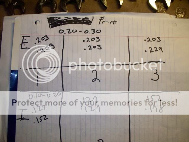
Yes most of them were on the tight end of things, and I have a feeling some adjustments will need to be made this time. I also may go ahead and replace the cam chain while I am in there.
 
Top